
Continuous in-line manufacturing process for high speed coating deposition via kinetic spray process

A technology of power spraying and power nozzles, which is applied in the field of coating substrates by power spraying technology, and can solve the problems that the traverse speed cannot be used and the traverse speed is slow

Inactive Publication Date: 2006-06-07
DELPHI TECH INC
View PDF3 Cites 4 Cited by
  • Summary
  • Abstract
  • Description
  • Claims
  • Application Information

AI Technical Summary

Problems solved by technology

This traverse velocity is too slow to be used when the manufacturing environment requires high deposition efficiency and high traverse velocity in the range of 25 to 250 cm / sec

Method used


Image

  • Continuous in-line manufacturing process for high speed coating deposition via kinetic spray process
  • Continuous in-line manufacturing process for high speed coating deposition via kinetic spray process
  • Continuous in-line manufacturing process for high speed coating deposition via kinetic spray process

Examples


Embodiment Construction

[0020] The present invention includes significant improvements over the power injection process and nozzle systems primarily described in US Patent Nos. 6,139,913 and 6,283,386.

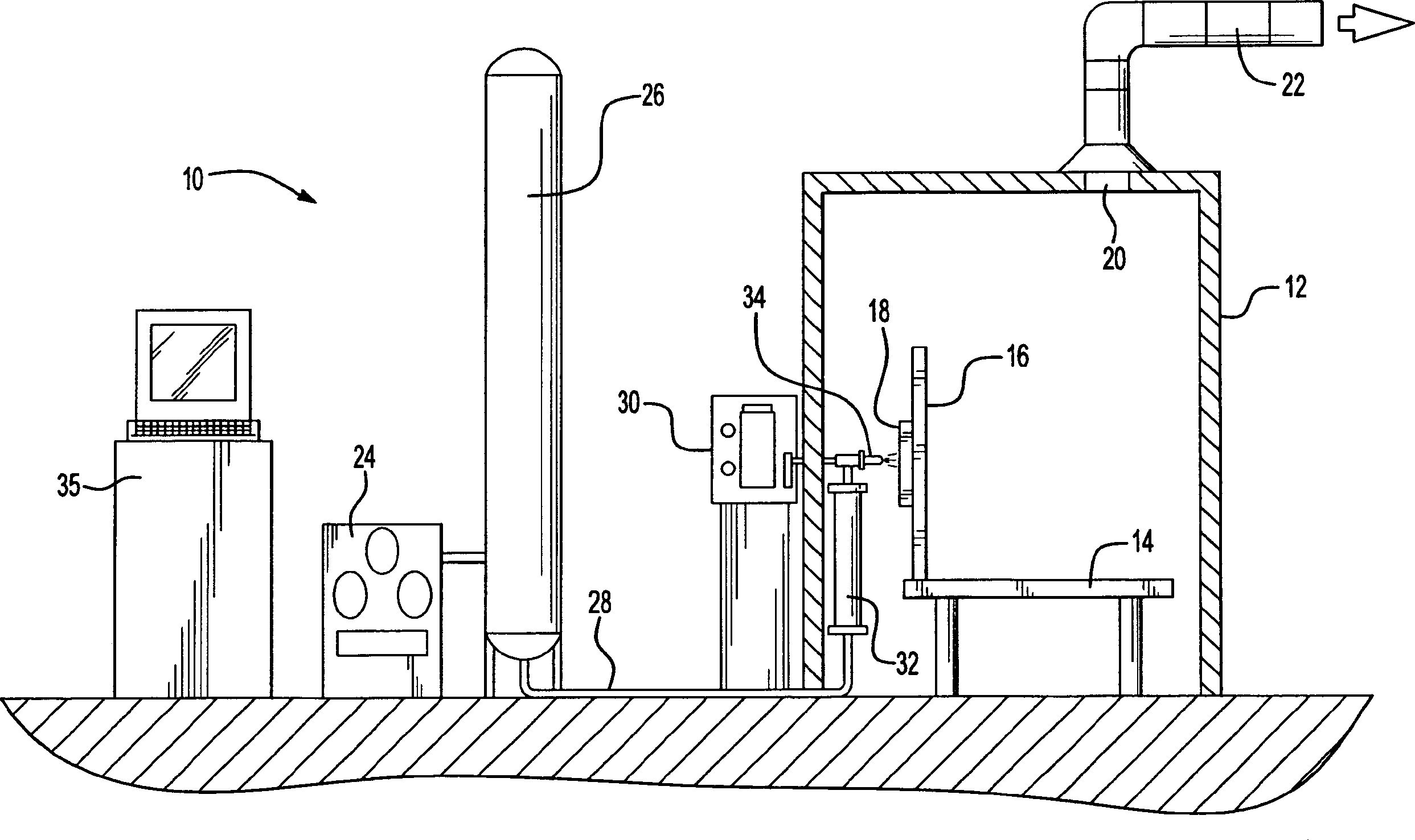
[0021] see first figure 1 , generally indicated at 10, a power injection system using nozzles designed in accordance with the present invention. The system 10 may include an enclosure 12 in which a support table 14 or other support means is located. A mounting plate 16 secured to the table 14 supports a workpiece holder 18 . The workpiece holder 18 can have a variety of configurations depending on the type of substrate to be coated. For example, the workpiece holder 18 may be configured for use with the present invention as a plurality of high speed rollers capable of moving the substrate through the nozzle 34 at traverse speeds in excess of 250 cm / sec. In other embodiments, the workpiece holder 18 may be capable of three-dimensional movement and capable of supporting a suitable workpiece formed f...


PUM

PropertyMeasurementUnit
lengthaaaaaaaaaa
lengthaaaaaaaaaa
diameteraaaaaaaaaa

Abstract

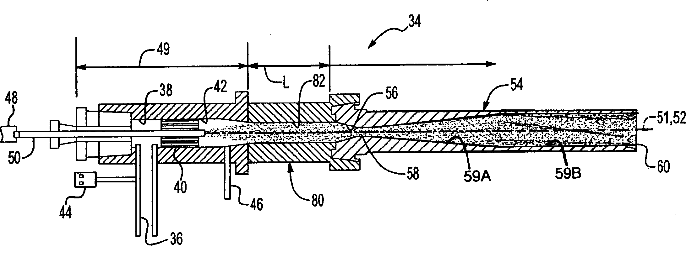
An improved power injection system and its method of use in a high speed manufacturing environment. The powered nozzle system comprises: a gas / powder exchange chamber connected to a first end of a regulating chamber having a length along a longitudinal axis equal to or greater than 20 mm; a convergent ultrasonic nozzle having a converging portion separated from a diverging portion by a throat, the diverging portion comprising a first portion of increasing cross-sectional area along its length and a second portion of substantially constant cross-sectional area along its length; and a converging portion connected to a second end of the adjustment cavity opposite said first end. The method includes: using a nozzle system with the addition of hard particles that allow for maximum particle temperature without clogging the nozzle; using controlled particle feed rates to accommodate very high traverse speeds; and preheating the substrate for cleaning substrate thereby enhancing particle binding properties. In conjunction with the disclosed nozzle systems and methods, kinetic spraying can be performed at traverse speeds in excess of 200 cm / s and deposition efficiencies in excess of 80%.

Description

[0001] references [0002] US Patent No. 6,139,913, "Power Spray Method and Apparatus" and US Patent No. 6,283,386, "Power Spray Apparatus" are incorporated herein by reference. technical field [0003] The present invention relates to coating substrates using the power spray process, and more particularly, the present invention relates to an improved nozzle system that allows high speed continuous in-line coating deposition using a power spray system. Background technique [0004] The prior art for power injection systems generally discloses a power injection system with a nozzle system comprising a gas / powder exchange chamber connected directly to a Laval-type convergent ultrasonic nozzle. The system introduces a flow of powder particles into the exchange chamber under positive pressure. Typically, the powder gas used to drive the powder into the exchange chamber is not heated to prevent the powder from clogging the powder ducts. The heated primary gas is also introduced...

Claims


Application Information

Patent Timeline
Patent Type & Authority Applications(China)
IPC IPC(8): B05B7/00B05B7/14B05B7/16
CPCC23C24/04B05B7/00B05D1/02B05D3/12
Inventor T·韩Z·赵B·A·吉利斯皮J·R·史密斯J·S·小罗森
Owner DELPHI TECH INC
Learn More