Phase error detection circuit and synchronization clock extraction circuit

A technology of phase error and detection circuit, which is applied in the direction of synchronous device, electrical components, and signal processing using self-timing code, which can solve the problem that the regeneration data cannot be obtained synchronously

Inactive Publication Date: 2006-06-07
PANASONIC CORP
View PDF1 Cites 5 Cited by
  • Summary
  • Abstract
  • Description
  • Claims
  • Application Information

AI Technical Summary

Problems solved by technology

[0014] The object of the present invention is to solve the above-mentioned problems, and to accurately d...

Method used


Image

  • Phase error detection circuit and synchronization clock extraction circuit
  • Phase error detection circuit and synchronization clock extraction circuit
  • Phase error detection circuit and synchronization clock extraction circuit

Examples


no. 1 Embodiment approach

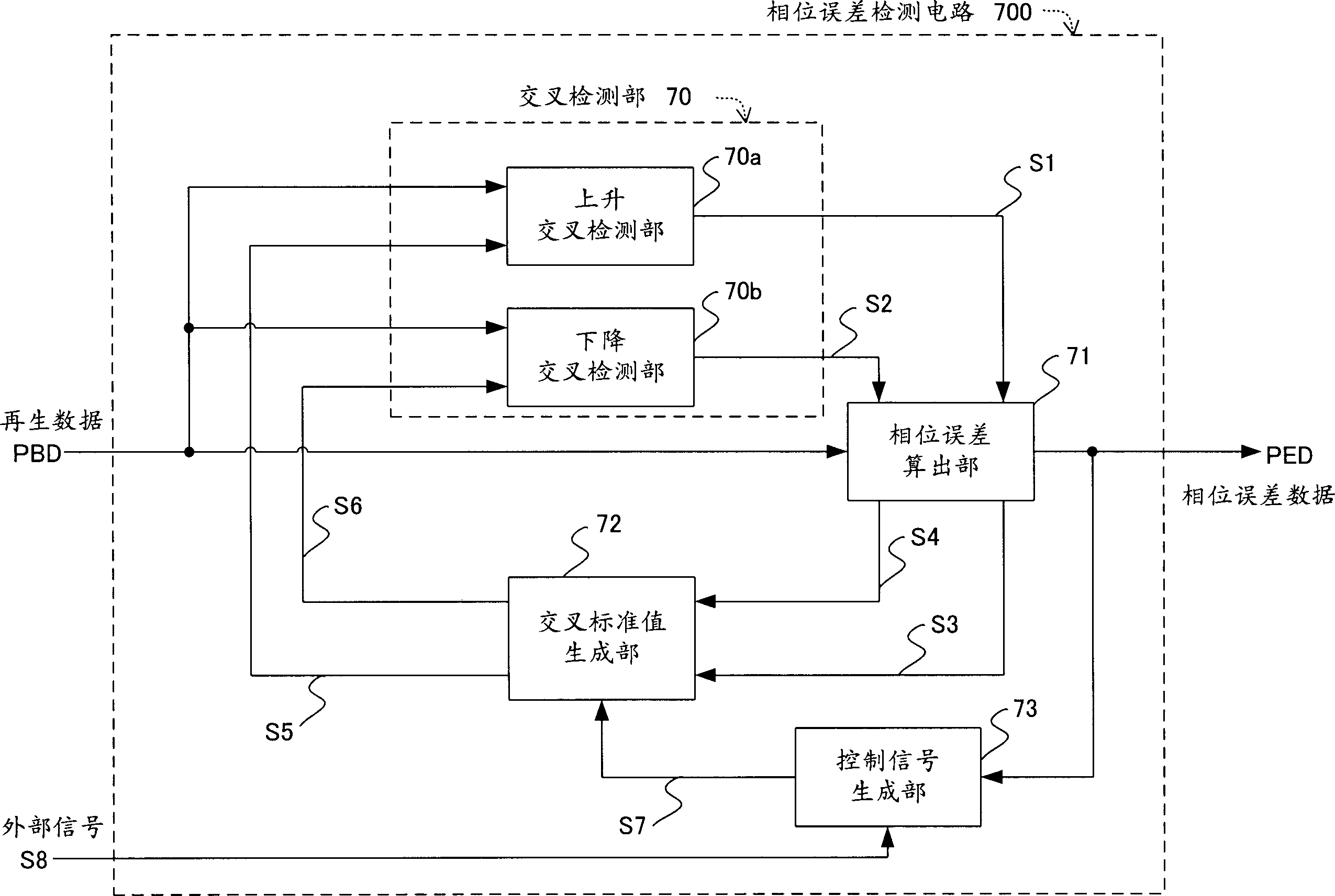
[0085] figure 1 , is a diagram showing a phase error detection circuit according to the first embodiment of the present invention. The phase error detection circuit in the same figure is in Figure 12 In the reproduced signal processing circuit of the optical disc device (recording and reproducing device) shown, a circuit replaces the phase comparator 7 included in the synchronous clock extraction circuit 13 of the digital signal processing circuit 12 . Therefore, the configuration of the synchronous clock extraction circuit or the reproduced signal processing circuit having the phase error detection circuit is different from that of Figure 12 The same, and its description is omitted.

[0086] figure 1 Among them, 700, is reproduced from the recording and reproducing device and in Figure 23 The shown A / D converter 4 AD conversion (digital) regenerative data detection phase error output phase error detection circuit, in Figure 12 In the synchronous clock extraction circu...

no. 2 Embodiment approach

[0102] Next, the phase error detection circuit in the second embodiment will be described. In this embodiment, the reference value generated by the intersection reference value generating unit 72 is different from that of the first embodiment.

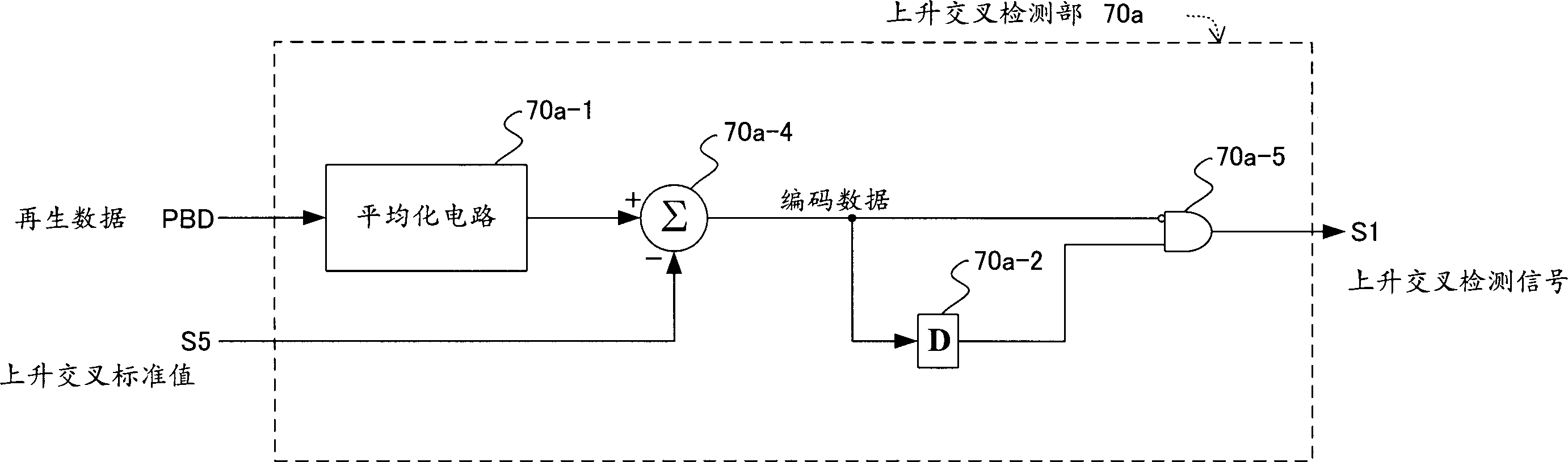
[0103] That is, using the input to figure 1 The rising phase error data S3 of the crossing reference value generating unit 72 outputs the rising reference value S5 to the rising detection unit 70a, and outputs the rising crossing reference value S5 of equal absolute value and opposite sign to the falling detection unit 70b. use Image 6 Describe the situation. Use the level Lr of the phase error data point PE1 at the rising time as a reference value to detect the phase error data point PE3 at the next rising time, and to detect the phase error data points PE4 and PE4 at the falling time by using the inverted phase at the rising time The value of the sign of the level Lr of the error data point PE1.

[0104] Therefore, as in the fi...

no. 3 Embodiment approach

[0106] Next, the phase error detection circuit in the third embodiment will be described. In this embodiment, another embodiment of reference value generation is shown.

[0107] That is, using the falling phase error data S4 input to the crossing reference value generation unit 72, the falling crossing reference value S6 is output to the falling crossing detection unit 70b, and the falling crossing reference value S6 with equal absolute value and opposite sign is output to the rising crossing detection unit 70a. These are used Figure 7 To illustrate, the phase error data point PE4 at the next falling time is detected with the level Lf of the detected phase error data point PE2 at the time of falling as a reference value, and in the detection of the phase error data point PE3 at the time of rising, it is reversed The value of the sign of the level Lf of the phase error data point PE2 at the time of the above-mentioned fall is a reference value.

[0108] Therefore, as in the ...


PUM


Abstract

In the phase error detection circuit of the synchronous clock extracting circuit for extracting the clock synchronized with the reproduced data, the cross reference value generating part (72) uses the rising phase error data (S3) calculated by the phase error calculating part (71) as rising The crossing reference value (S5) is input to the ascending crossing detection unit (70a), and the calculated descending phase error data (S4) is similarly output to the descending crossing detection unit (70b) as the descending crossing reference value (S6). The two intersection detection parts (70a, 70b) respectively calculate the difference between the regeneration data value of the sample point and the above-mentioned input cross reference value (cross deviation value) (S5, S6), when one of the two difference values ​​of the continuous sample points When one is negative and the other is positive, the rising and falling cross detection signals are output. Therefore, the capture band is expanded.

Description

technical field [0001] The present invention relates to a phase error detection circuit for extracting the recorded data from a recording medium such as an optical disc or a magnetic disk, and for extracting a synchronous clock in a reproduction signal processing circuit for extracting a synchronous clock. Background technique [0002] An example of a reproduced signal processing circuit in a conventional optical disc device is used as Figure 12 express. [0003] Figure 12 Among them, 1 is a recording medium such as an optical disc, 2 is an optical head, 3 is an analog tuner, and 12 is a digital signal processing circuit. In the above-mentioned digital signal processing circuit 12, 4 is an A / D converter, 5 is a digital filter, 6 is a decoder, and 13 is a synchronous clock extraction circuit. In the synchronous clock extraction circuit 13, 7 is a phase comparator, 8 and 11 are loop filters, 9 is a voltage controlled oscillator (VCO), and 10 is a frequency comparator. The ...

Claims


Application Information

Patent Timeline
IPC IPC(8): G11B20/14H04L7/033
Inventor 河边章冈本好史
Owner PANASONIC CORP
Why Eureka
Try Eureka