Conveying device

A technology for conveying devices and conveying paths, which is applied in the direction of conveyor control devices, conveyors, transmission devices, etc., can solve problems such as uneven rotation, low precision of transmission distance, and overall enlargement of the device, achieving excellent durability, Improved wear resistance and high-precision movement effects

Active Publication Date: 2006-06-14
YAMAKYU CHAIN
View PDF0 Cites 15 Cited by
  • Summary
  • Abstract
  • Description
  • Claims
  • Application Information

AI Technical Summary

Problems solved by technology

[0005] However, in conventional conveying devices, since the circular arc of the sprocket teeth and the chain rollers cannot be completely restrained, backlash often occurs, resulting in uneven rotation or low accuracy of transmission distance.
[0006] In addition, since polygonal motion is performed on the driving side and the driven side, a polygonal effect (coordinate effect) occurs and the center distance changes. For this, a buffer mechanism such as a spring is used to absorb the play of the chain itself. backlash, slack, or play at the point where the sprocket teeth mesh with the chain rollers, etc., but there is still a problem that high rotation accuracy cannot be obtained.
[0007] In particular, in the case of a sprocket with six teeth, since the center distance fluctuates significantly, the tension of the chain cannot be increased, and it is not suitable for precision conveyance.
[0008] In addition, although the conventional precision chain mechanism can provide a structure that does not have the problem of chain accuracy or play, for the sprocket, even if the machining accuracy of its teeth is improved, there is still the problem that the play cannot be completely eliminated.
[0009] In addition, in order to suppress the fluctuation of the center distance as much as possible, the chain tension is reduced by reducing the chain pitch and increasing the number of teeth of the sprocket. However, there are more restrictions on the general-purpose jigs installed on the chain. There will be a problem that the overall size of the device will be increased

Method used


Image

  • Conveying device
  • Conveying device
  • Conveying device

Examples


Embodiment Construction

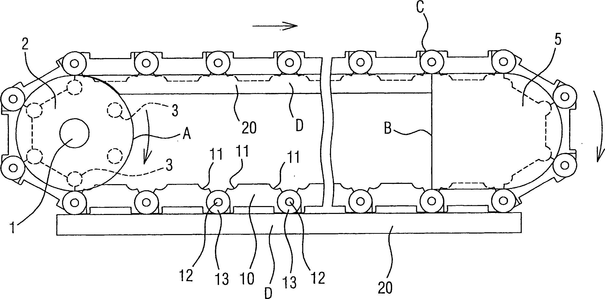
[0053] The present invention mainly provides a conveying device capable of precise linear conveying without backlash, for example, using figure 1 The illustrated embodiment embodies the conveying device, which is characterized in that it includes: a sprocket A rotated by a drive unit; a guide body B arranged on a desired conveying path; The chain C on the top; the walking guide rail D, which is arranged on the conveying path connecting the sprocket A and the guide body B in order to guide the chain C; and the rail guide unit, which connects the walking guide rail D and the chain C, so that the chain C can Move along the walking guide rail D.

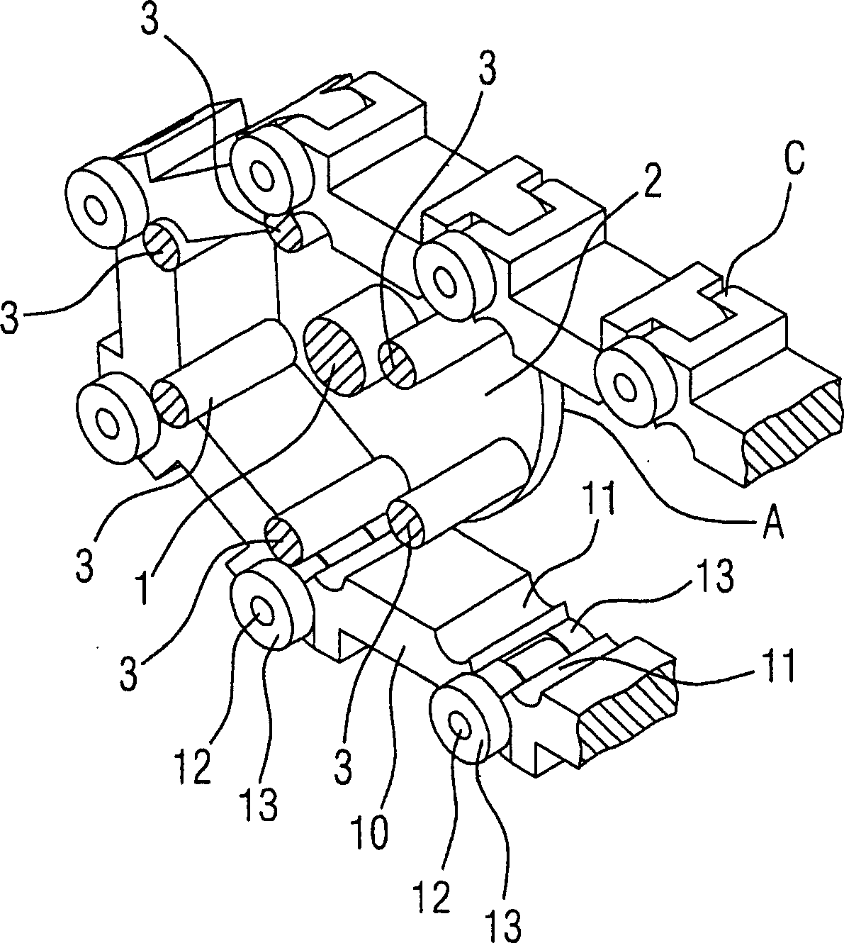
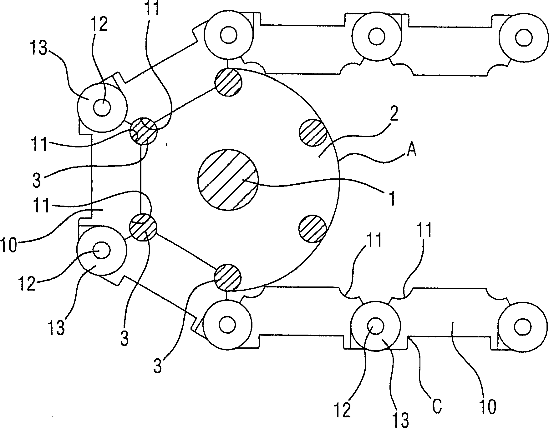
[0054] In addition, the above-mentioned sprocket A has: a pair of rotating base plates 2 arranged at a predetermined interval; ;

[0055] The guide body B has a pair of guide substrates 5 arranged at a predetermined interval;

[0056] The above-mentioned chain C has: a plurality of connecting rods 10; connecting pins 12, connecting t...


PUM


Abstract

To provide a conveying apparatus, achieving complete constraint without play to cause no backlash and uneven rotation, having high accuracy of transfer conveying distance, attaining high rotational accuracy, performing precise linear conveyance, having little limitation on general-purpose tools, constructed compact, having excellent wear resistance, restraining elongation, simple in construction,having high durability, suitable for mass production, and economical. This conveying apparatus includes a sprocket A, a guide body B and a chain C, wherein the sprocket A has a rotary base plate 2 and a plurality of cylindrical teeth 3, the guide body B has a pair of guide plates 5, and the chain C has a plurality of links 10 and a connecting pin 12. Both end parts in the conveying direction of the link 10 are provided with a curved recessed surface 11 coming into close contact with the outer peripheral surface of the cylindrical tooth 3. A locking groove formed of a pair of adjacent curved recessed surfaces 11 to be locked on the cylindrical tooth 3 is deformed with mutual locking of the links 10 and brought into close contact with the outer peripheral surface of the cylindrical tooth 3 at the rotational force transmitting position of the sprocket A.

Description

technical field [0001] The present invention mainly relates to a conveying device designed among conveying devices using a chain, for example, capable of precise linear conveying without backlash. Background technique [0002] Conventionally, various proposals have been made as such a conveying device using a chain. For example, in conventional precision chains, bearings are used for the rollers, and the rollers mesh with sprocket teeth without backlash. [0003] In addition, according to the relationship between the rotating chain pitch and the number of teeth of the sprocket, the chain simultaneously performs polygonal motion on the driving side and the driven side, thus producing a polygonal effect (when the bearing center of the chain meshes with the sprocket, the pitch circle forms polygonal phenomenon), resulting in a constant change in the center distance. [0004] For example, if Figure 11 As shown in (I) to (II), when a chain with a pitch (P) is wound around a pa...

Claims


Application Information

Patent Timeline
Patent Type & Authority Applications(China)
IPC IPC(8): B65G17/00B65G17/38B65G21/20B65G23/04
CPCB65G15/62B65G23/38B65G43/00B65G47/844F16H7/06F16H55/30
Inventor 前田富男加藤福和
Owner YAMAKYU CHAIN
Why Eureka
Try Eureka