Expansion device

A technology of expansion device and valve body, which is applied in the direction of fluid circulation arrangement, refrigeration components, refrigerators, etc., can solve the problems of insufficient cooling capacity, large overlap between valve hole and valve body, insufficient flow rate and set flow rate, etc. , to achieve the effect of ensuring cooling capacity, reducing abnormal noise, and reducing inhalation phenomenon

Inactive Publication Date: 2006-06-14
TGK
View PDF2 Cites 5 Cited by
  • Summary
  • Abstract
  • Description
  • Claims
  • Application Information

AI Technical Summary

Problems solved by technology

[0006] However, in the conventional expansion device, the anti-vibration spring mounted on the valve body is pressed against the inner wall surface of the casing as a measure to prevent abnormal noise, so the frictional force between the wall surface and the wall surface increases. Larger, the flow characteristics of the valve produce a large hysteresis, so that the valve body deviates from the design position designed as the best position, so there is a problem that the efficiency of the refrigeration cycle deteriorates
[0007] In addition, in CO 2 In the existing expansion device composed of a differential pressure regulating valve used in the refrigeration cycle of the refrigerant, the diameter of the valve body th

Method used


Image

  • Expansion device
  • Expansion device
  • Expansion device

Examples


Embodiment Construction

[0024] Below, referring to the accompanying drawings, to be applied to the use of CO 2 Embodiments of the present invention will be described in detail using the case of a refrigeration cycle of a vehicle air conditioner as a refrigerant as an example.

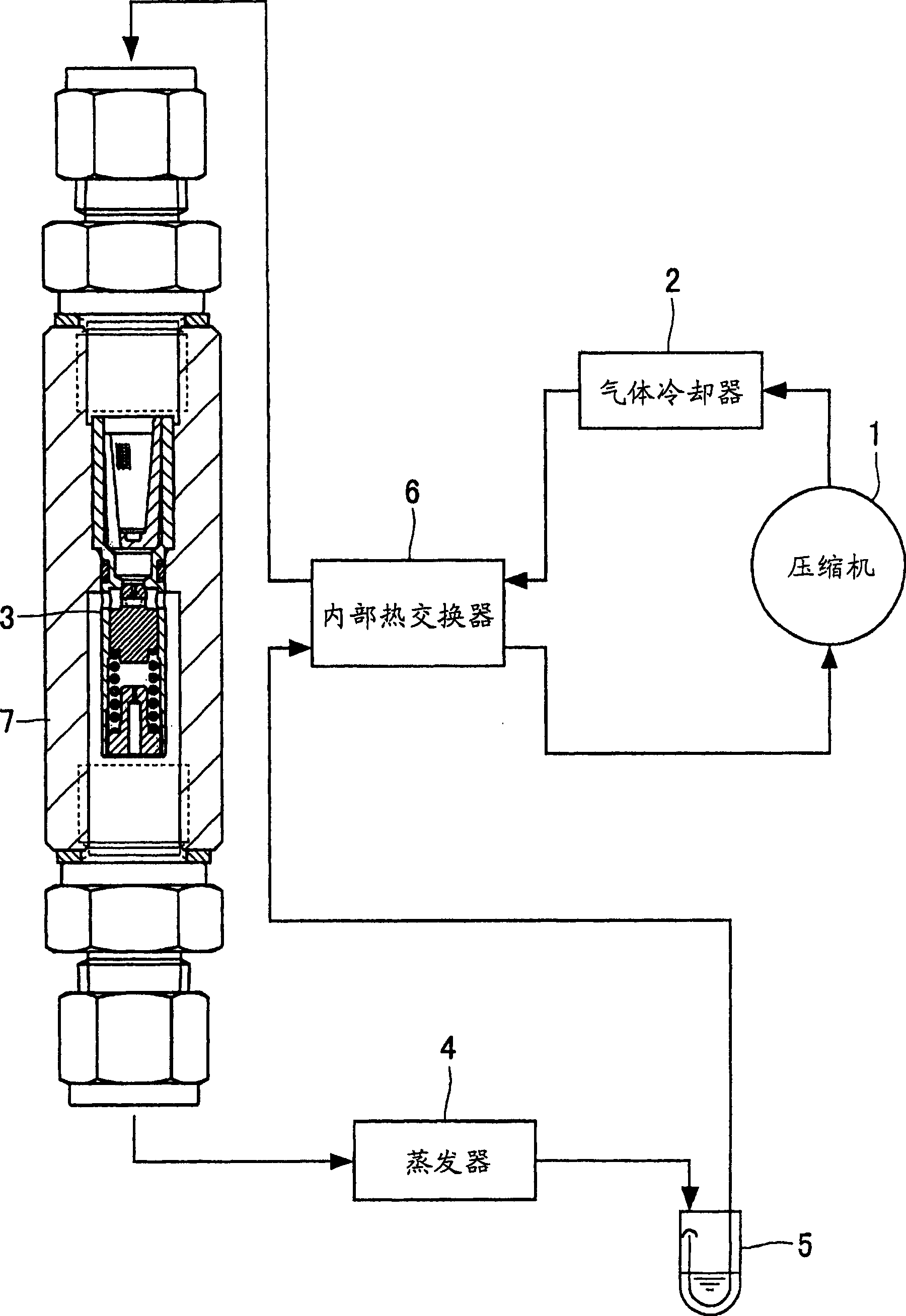
[0025] figure 1 is a schematic diagram of a refrigeration cycle using the expansion device of the present invention.

[0026] The refrigeration cycle includes: a compressor 1 for compressing refrigerant; a gas cooler 2 for cooling the compressed refrigerant; an expansion device 3 for adiabatically expanding the cooled refrigerant; The evaporator 4 where the expanded refrigerant evaporates; the liquid separation reservoir 5, which is provided on the downstream side of the evaporator 4, for storing the remaining refrigerant; the internal heat exchanger 6, which utilizes the The refrigerant sent to the compressor 1 cools the refrigerant cooled in the gas cooler 2 .

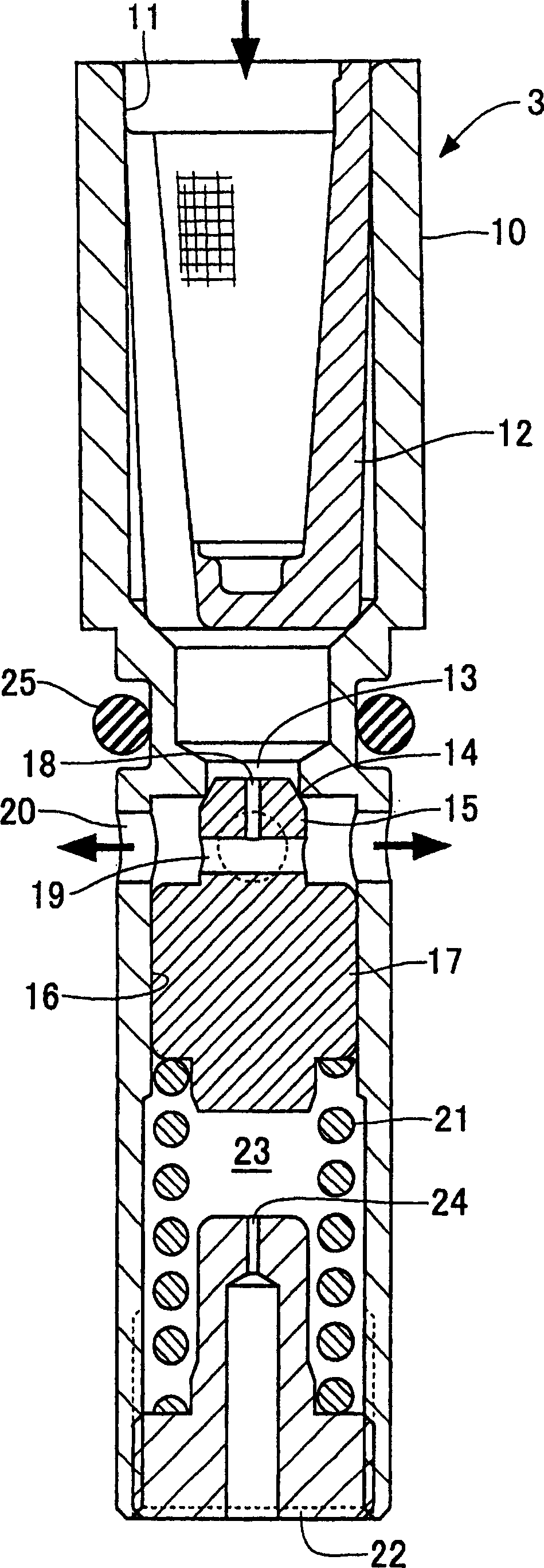
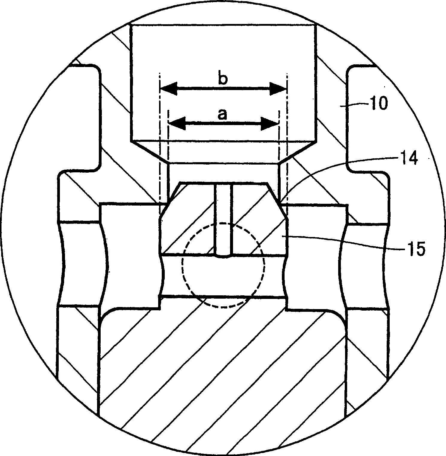
[0027] The expansion device 3 is provided inside the cylind...


PUM


Abstract

An expansion device that reduces abnormal noise due to vibration of a valve body and reduces valve body suction phenomenon caused by high-pressure refrigerant flowing through a variable hole formed between a valve seat and the valve body produced. In the expansion device, the buffer chamber (23) is composed of the following components: cylinder (16), formed in the housing (10) forming the valve seat (14); piston (17), which is formed with the valve body (15) as One piece; the adjusting screw (22), when the valve body is subjected to the sudden pressure change of the introduced refrigerant, absorbs the violent action of the valve body through the volume change of the buffer chamber, thereby suppressing the vibration of the valve body (15), thereby reducing Unusual noise generation. Make the ratio (b/a) of the valve body diameter (b) of the valve body (15) to the valve port diameter (a) of the valve hole less than or equal to 1.5, so as to reduce the suction phenomenon of the valve body, and make the refrigerant flow with the primary pressure and The pressure difference between the secondary pressures corresponds to the flow through.

Description

technical field [0001] The invention relates to an expansion device used in the refrigeration cycle of a vehicle air conditioner, in particular to an expansion device applicable to carbon dioxide (CO 2 ) as the expansion device of the refrigeration cycle of the refrigerant. Background technique [0002] As a refrigeration cycle of an air conditioner for a vehicle, a refrigeration cycle having a receiver for gas-liquid separation of refrigerant condensed in a condenser and a temperature type expansion valve is generally used, so The temperature type expansion valve expands the separated liquid refrigerant. In contrast, a refrigeration cycle using an expansion device (orifice) and a separatory accumulator (accumulator) is also known, wherein the expansion device (orifice) is used to throttle the refrigerant condensed in the condenser and make it Expansion, the liquid separation storage is used for gas-liquid separation of the refrigerant evaporated in the evaporator. [000...

Claims


Application Information

Patent Timeline
IPC IPC(8): F25B41/06
Inventor 津川德巳利根川正明
Owner TGK
Why Eureka
Try Eureka