Apparatus for producing multi pulse by Dammann grating pair

A Daman grating and multi-pulse technology is applied in the field of devices that generate multi-pulse, can solve problems such as low cost, and achieve the effect of low cost and easy fabrication

Inactive Publication Date: 2006-06-14
SHANGHAI INST OF OPTICS & FINE MECHANICS CHINESE ACAD OF SCI
View PDF0 Cites 10 Cited by
  • Summary
  • Abstract
  • Description
  • Claims
  • Application Information

AI Technical Summary

Problems solved by technology

It is required that the production is easier and the cost is relatively low

Method used


Image

  • Apparatus for producing multi pulse by Dammann grating pair
  • Apparatus for producing multi pulse by Dammann grating pair
  • Apparatus for producing multi pulse by Dammann grating pair

Examples


Embodiment 1

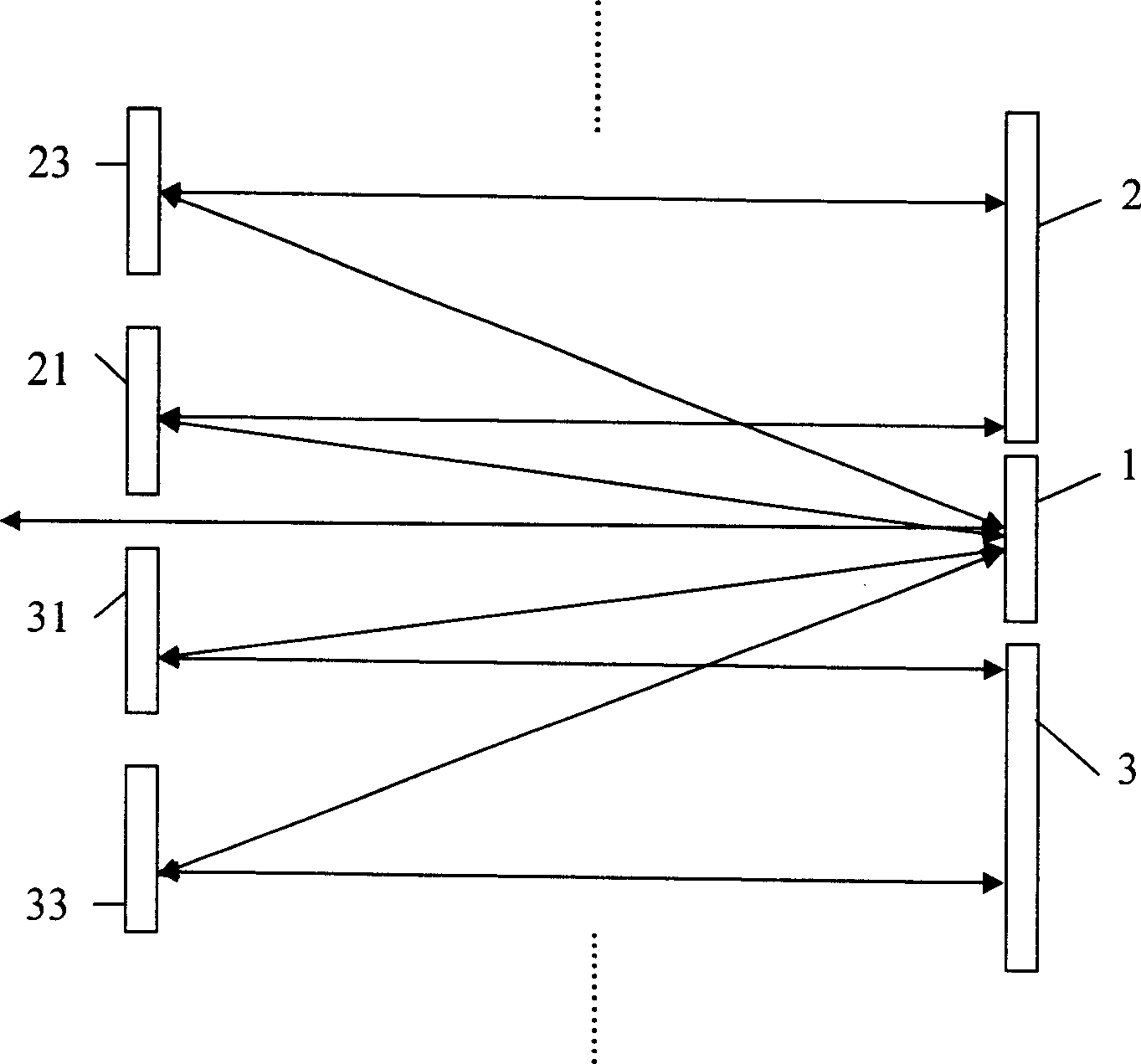
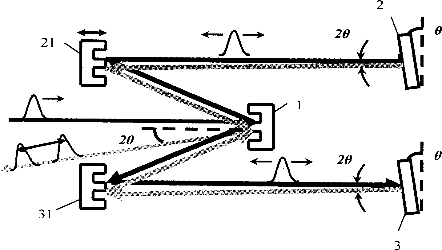
[0049] Such as figure 2 As shown, the main grating 1 is a 1×2 reflective Damman grating with a period of 25 μm, and two completely identical 1×2 reflective first-stage Damman gratings 21 and 31 are placed at a distance of 30 cm as compensation gratings; The symmetry axes of the primary Damman gratings 21, 31 are on the normal line of the main grating 1, and the normal directions of the main grating 1 and the primary Damman gratings 21, 31 are parallel. The horizontal distance between the two centers is 2cm. Place the first total reflection mirror 2 and the second total reflection mirror 3 apart from the first-order Damman grating 21,31-35cm;

[0050] The laser pulse with positive chirp is incident on the main grating 1, and its positive and negative first-order diffracted lights are respectively incident on the first-order Damman grating 21, 31; the reflected light is reflected by the first total reflection mirror 2 and the second total reflection mirror 3 , the surface of ...

Embodiment 2

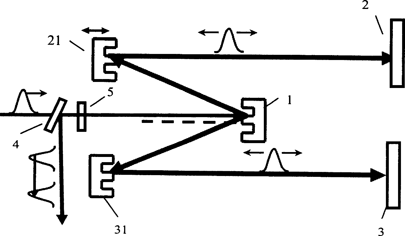
[0052] We can separate the input and output light in another way. Such as image 3 As shown, on the normal line of the main grating 1, that is, along the direction of the incident light, a polarizing dielectric template 4 and a 1 / 4 wave plate 5 that are 45° to the optical path are arranged in sequence, and the polarizing dielectric template 4 is opposite to the 45° incident light P-polarized light is completely transparent, while S-polarized light is completely reflected. If the incident light is p-polarized, the output light will become s-polarized due to passing through the 1 / 4 wave plate 5 twice. The p-polarized light is transmitted, and the s-polarized light is totally reflected at 45°, so that the output light and the input light are separated.

Embodiment 3

[0054] The structures of this embodiment and embodiment 2 are basically the same, as Figure 4As shown, when the diameter Φ of the first total reflection mirror 2 and the second total reflection mirror 3 is constant, the distance s between them and the primary Damman grating 21, 31 is not arbitrary, and if s is too small, it will hinder the main grating 1 diffracted light, so there is a minimum s min =Φctgα; α is the diffraction angle of the positive and negative order of the Damman grating used.

[0055] In the experiment, the input pulse measured by the standard second harmonic frequency resolution optical switch device is a double pulse with a chirp of 0.00031 rad / fs, an input pulse of 88.5 fs, and an output pulse of 46.2 fs, which has obvious pulse compression. By adjusting the first-stage Damman gratings 21, 31, a series of double pulses with different pulse intervals can be obtained.


PUM


Abstract

The invention relates to producing multi-pulse equipment by Dammann grating set. Its structure includes a main grating. It is 1xn reflection type Dammann grating, n is the positive integer. The n/2 blocks reflection type compensating grating is set at L distance, two sides of the normal line, and diffracted light direction. Each of them is first grade, third grade, and fifth grade Dammann gratings. The distance between each two Dammann gratings is b. The period of the main grating is d. The third grade is d/3. The fifth grade is d/5. The first and second holophotes are set at s distance between main grating two sides to the working surface of the compensating grating. It also includes separating mechanism used to separate output light form input light. The invention can realize compression for positive chatter pulse and form multi-pulse with identical wavelength and adjustable pulse interval.

Description

technical field [0001] The invention relates to a Damman grating, in particular to a device for generating multiple pulses using a Damman grating pair technical background [0002] Usually, a grating pair is used as a device with negative dispersion properties to compress laser pulses. Most of the gratings used are high-density gratings (1000 lines / mm-2000 lines / mm), the production of gratings is relatively difficult and the cost is high; and the device cannot generate multiple pulses; ordinary gratings will cause differences in the intensity of each diffraction order It is very large, and it is difficult to obtain multiple pulses in the device we mentioned below. [0003] A common way to generate double pulses is through a Michelson interferometer, and there are also double-wavelength double-pulse devices, but none of them can compress the input pulse. [0004] A Damman grating with too low line density (less than 10 lines / mm) has no compression effect on the pulse; if th...

Claims


Application Information

Patent Timeline
Patent Type & Authority Applications(China)
IPC IPC(8): G02B5/18G02B27/44
Inventor 白冰周常河戴恩文
Owner SHANGHAI INST OF OPTICS & FINE MECHANICS CHINESE ACAD OF SCI
Why Eureka
Try Eureka