High frequency switch transformer

A high-frequency transformer and high-frequency switch technology, applied in the direction of transformer/inductor cooling, transformer/inductor coil/winding/connection, etc., to achieve the effect of low temperature rise, solving skin effect and cooling requirements, and improving heat dissipation effect

Inactive Publication Date: 2006-06-14
中山市怡能捷高工业自动化设备有限公司
View PDF0 Cites 3 Cited by
  • Summary
  • Abstract
  • Description
  • Claims
  • Application Information

AI Technical Summary

Problems solved by technology

[0003] The first purpose of the utility model is to solve the heat dissipation problem of the high-frequency switching transformer

Method used


Image

  • High frequency switch transformer
  • High frequency switch transformer
  • High frequency switch transformer

Examples


Embodiment Construction

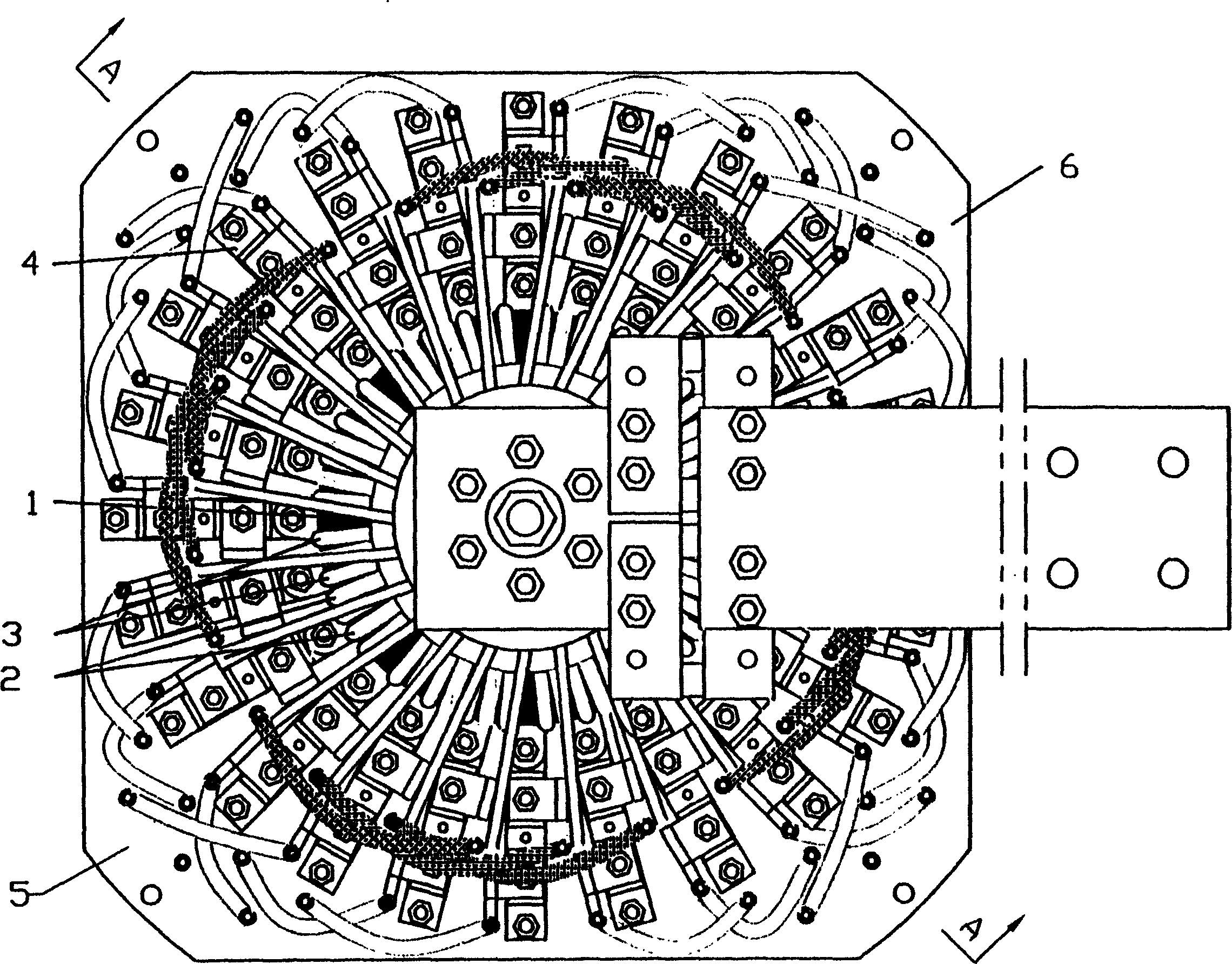
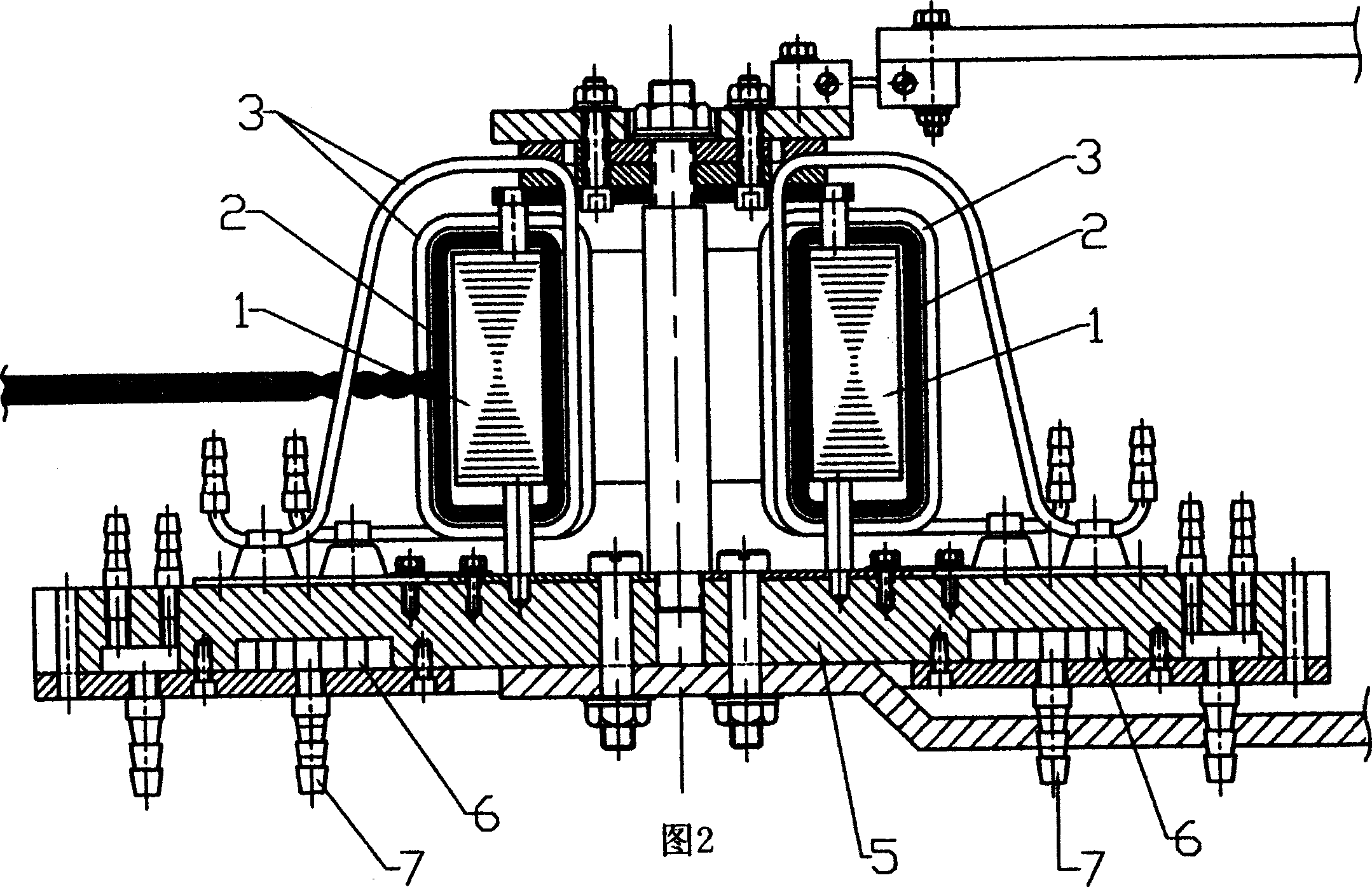
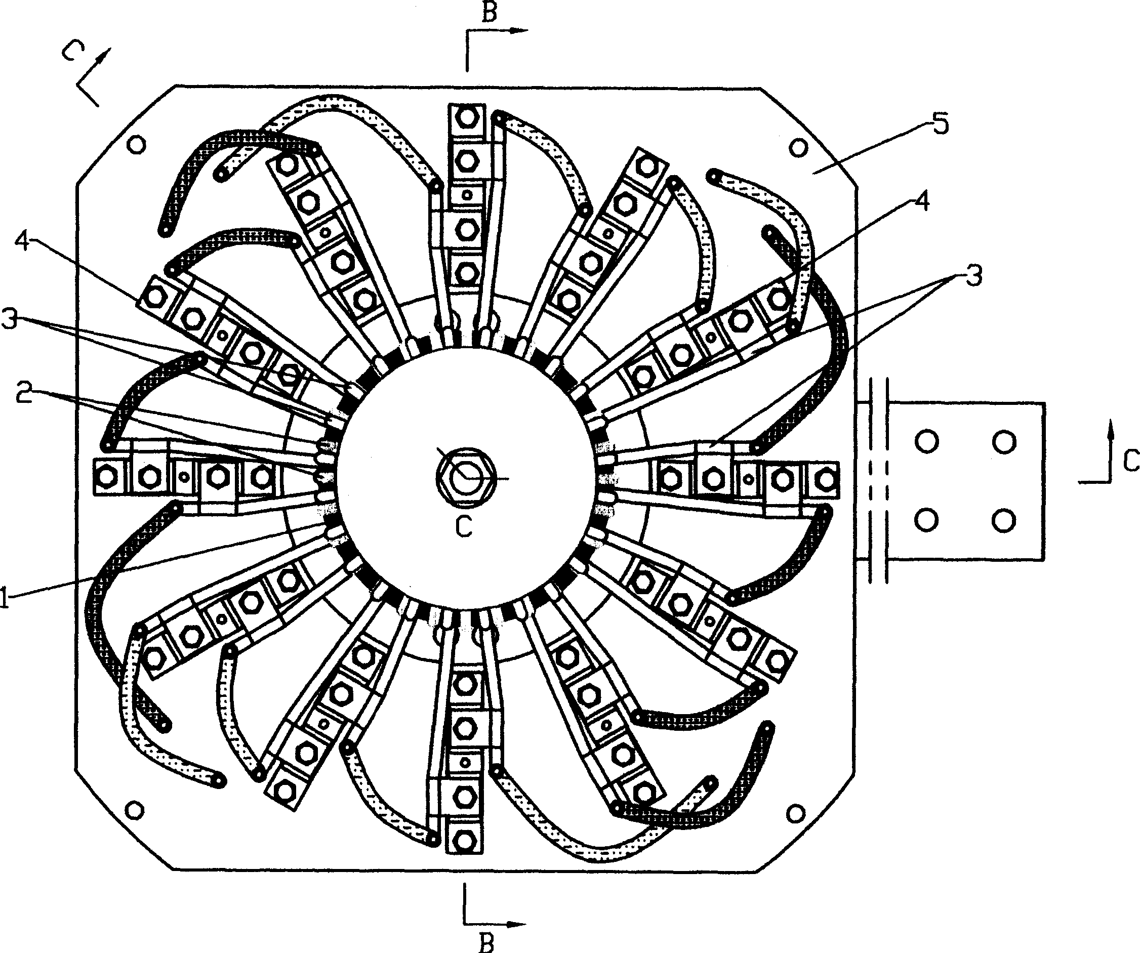
[0017] refer to figure 1 , Figure 2, a high-frequency switching transformer, the primary winding 2 and secondary winding system of the high-frequency transformer are formed by winding a hollow copper tube on a high-frequency magnetic core 1. The secondary winding system is composed of a plurality of individual secondary windings 3 connected in parallel, each individual secondary winding 3 and the primary winding 2 are evenly wound on the high-frequency magnetic core 1 in an alternate manner, and each high-frequency rectifier tube 4. Taking the central axis of the high-frequency switching transformer as the axis, they are evenly distributed radially and radially, and are connected to the individual secondary windings 3 in one-to-one correspondence.

[0018] When in use, the cooling water is connected to the nozzle 31 of the copper tube forming the secondary winding and the end of the copper tube forming the primary winding, which well solves the skin effect and cooling requirem...


PUM


Abstract

The invention discloses a high frequency transformer whose primary and secondary windings are each coiled of a hollow tubular conductor on a high frequency magnetic core. The center of each hollow tubular conductor is filled with cooling water or other medium, which perfectly solves the skin effect of high frequency current and the cooling requirement. As compared with the secondary cooling switching power transformer, the cooling effect is obviously improved to largely reduce the temperature increment of the switching power transformer.

Description

【Technical field】 [0001] The utility model relates to the overall structure of a high-frequency switching transformer in a water-cooled high-power switching power supply. 【Background technique】 [0002] Due to its small size, light weight and high efficiency, switching power supplies are becoming more and more popular in the society; in recent years, the output power demanded by society has been increasing, and the output current has reached the requirements of tens of thousands of amperes; however, the single power electronic device The current level of the tube cannot keep up with the demand, and each manufacturer uses multiple devices in parallel, which causes a series of problems such as current sharing problems between components, heat dissipation problems of the machine, and difficulty in ensuring reliability. 【Content of invention】 [0003] The first purpose of the utility model is to solve the heat dissipation problem of the high-frequency switching transformer ...

Claims


Application Information

Patent Timeline
Patent Type & Authority Applications(China)
IPC IPC(8): H01F27/28H01F27/08
Inventor 李铭鸿赵卫兵
Owner 中山市怡能捷高工业自动化设备有限公司
Why Eureka
Try Eureka