
Cold light piece driving circuit

A driving circuit and cold light chip technology, applied in the field of electricity, can solve the problems that it is difficult to ensure the stable operation of the driver, affect the service life of the driver, have no overvoltage, overcurrent and overheat protection, etc., and achieve rich flashing, light weight, and small size Effect

Inactive Publication Date: 2006-06-14
EL LIGHT
View PDF0 Cites 0 Cited by
  • Summary
  • Abstract
  • Description
  • Claims
  • Application Information

AI Technical Summary

Problems solved by technology

[0003] The technical problem in the prior art to be solved by the present invention is: since in the prior art, the EL driver adopts the design of self-excited oscillation, the operating frequency is 400 to 1500 Hz, and this frequency band is the most sensitive to the human ear, so it will It produces unbearable noise for the human ear. In addition, most of the EL drivers in the prior art do not have overvoltage, overcurrent and overheat protection, and it is difficult to ensure the stable operation of the driver and affect the service life of the driver.

Method used


Image

  • Cold light piece driving circuit

Examples


Embodiment Construction

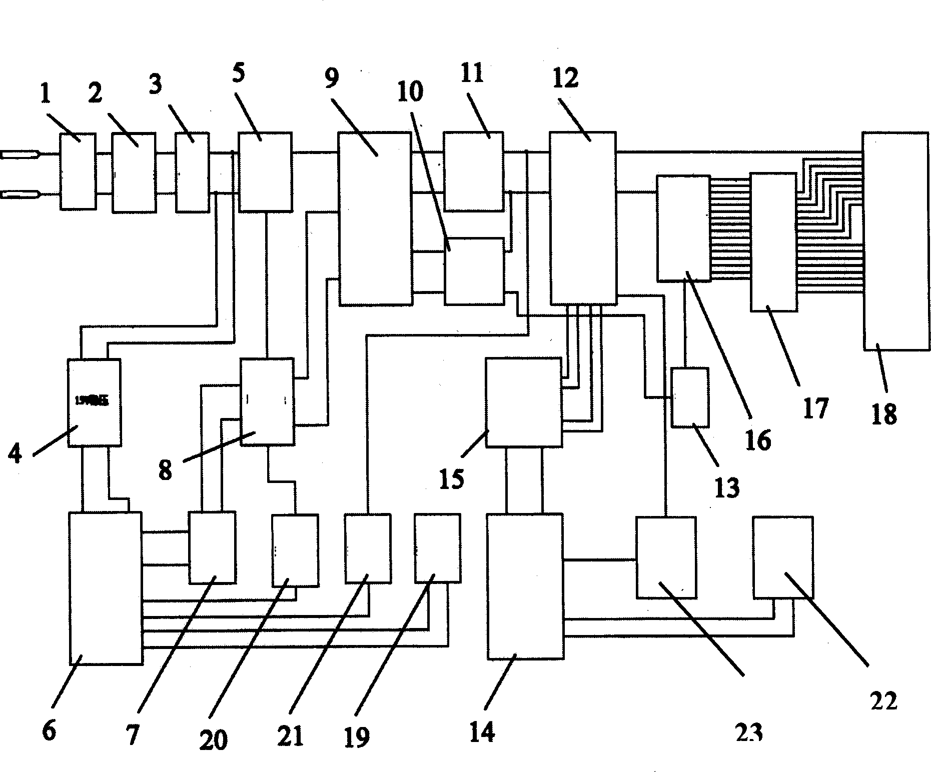
[0010] Such as figure 1 As shown in Fig. 2, the EL driving circuit of the present invention is composed of a power input circuit, a load output circuit, a transformer circuit, a first PWM pulse width modulation circuit, a second PWM pulse width modulation circuit, an inverter Circuit and a single-chip microcomputer control circuit 16 constitute, described power supply input circuit, load output circuit, transformer circuit, the first PWM pulse width modulation circuit, the second PWM pulse width modulation circuit, inverter circuit and single-chip microcomputer control circuit are all arranged on On the circuit board, wherein the power input circuit is composed of a DC power input terminal 1, a power switch 2 and a fuse 3, and the DC power input terminal 1 is connected to the fuse 3 through the power switch 2, The power input circuit is connected with a first voltage stabilizing circuit 4, and the first voltage stabilizing circuit 4 is connected with the first PWM pulse width ...


PUM


Abstract

A cold light drive circuit is composed of a supply input circuit, a load output circuit, a transformation circuit, a first PWM pulse width modulation circuit, a second PWM pulse width modulation circuit, an inverse circuit and a chip-microcomputer control circuit, in which, said circuits are all set on a CB and a switch technology, inverse supply technology and a chip-microcomputer control technology are applied to enable the driver to work stably and safely without any noises.

Description

technical field [0001] The invention relates to the field of electricity, in particular to a driving circuit of a light-emitting element, in particular to a driving circuit of a cold light sheet. Background technique [0002] In the prior art, the EL driver adopts the self-oscillating design, and the operating frequency ranges from 400 to 1500 Hz. This frequency band is the most sensitive to the human ear, so it will generate unbearable noise for the human ear. In addition, the prior art Most EL drivers do not have over-voltage, over-current and over-heat protections, and it is not easy to ensure the stable operation of the driver, which will affect the service life of the driver. Contents of the invention [0003] The technical problem in the prior art to be solved by the present invention is: since in the prior art, the EL driver adopts the design of self-excited oscillation, the operating frequency is 400 to 1500 Hz, and this frequency band is the most sensitive to the ...

Claims


Application Information

Patent Timeline
Patent Type & Authority Applications(China)
IPC IPC(8): H05B41/288H05B41/292
Inventor 陈瑞家
Owner EL LIGHT
Learn More