Solution agitating method and sample cell using for the method
A stirring method and solution technology, which is applied in the direction of chemical instruments and methods, dissolution, suspension and porous material analysis, etc., can solve the problems of increased blank time and reduced precision
- Summary
- Abstract
- Description
- Claims
- Application Information
AI Technical Summary
Problems solved by technology
Method used
Image

Examples
Embodiment approach 1
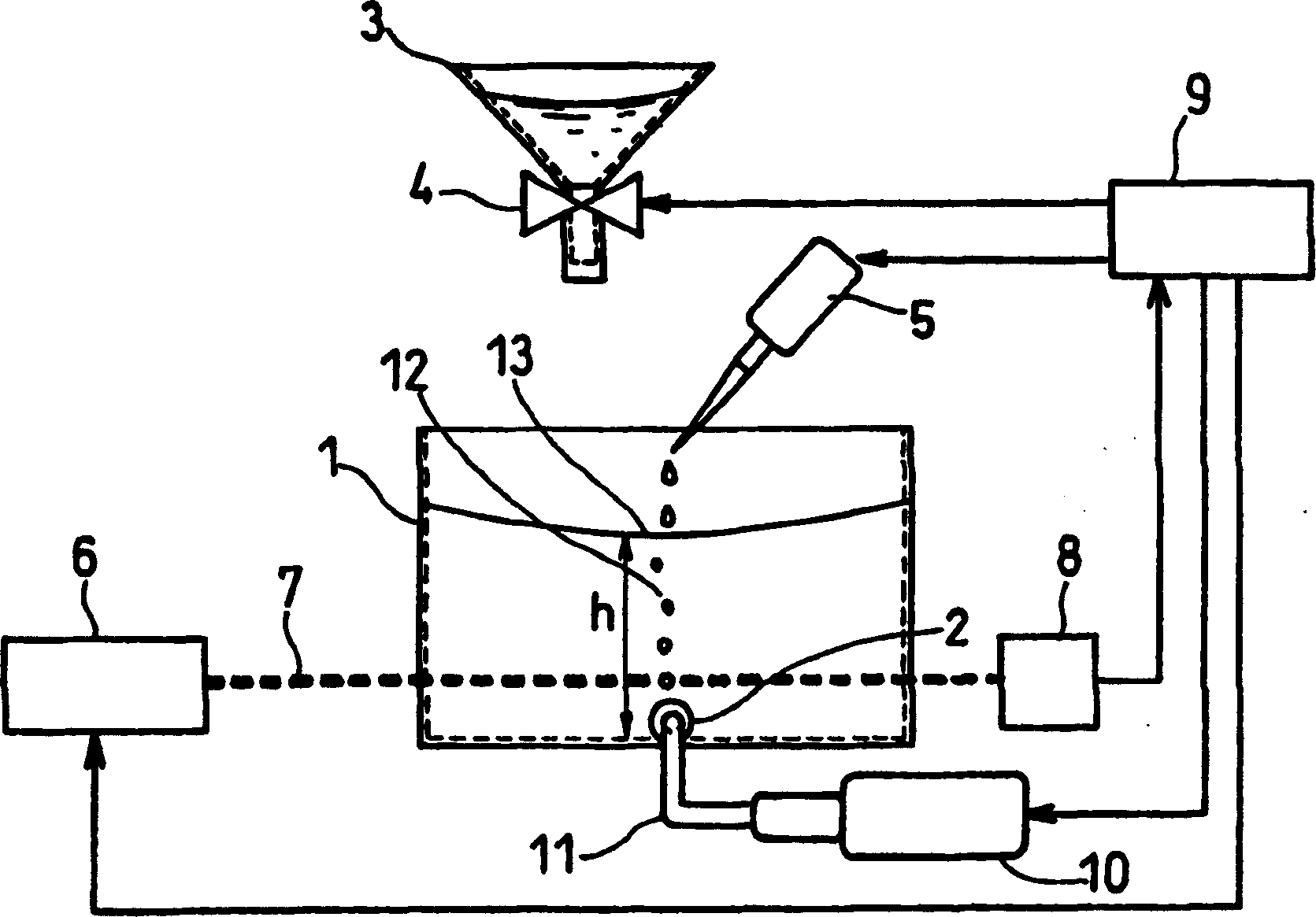
[0034] Below, use figure 1 Embodiments of the present invention will be described in detail.
[0035] figure 1 Among them, the skeleton part 1 of the sample cell of the present invention is composed of a cuboid aluminum container having an open opening at the top. Moreover, glass plates (not shown) as optical windows are embedded at both ends of the optical path, and light can pass through the measured solution while the measured solution is kept. figure 1 It is a figure showing the structure of the sample cell of this invention.
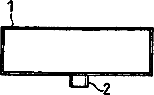
[0036] The distance in the long axis direction of the container, that is, the distance between the optical windows was 5 cm. In addition, the distance in the minor axis direction was 1 cm. The lowermost part of the skeleton part 1 of the sample cell is as figure 2 As shown, the injection port 2 is provided on the side without the optical window. in addition, figure 2 yes figure 1 Top view of skeleton part 1 of the sample cell shown. In es...
Embodiment approach 2
[0060] In this embodiment, the use of the figure 1 The sample cell having the structure shown above is an example of measuring the protein concentration in a test solution using a sulfosalicylic acid reagent solution (reagent obtained by dissolving sodium sulfate in an aqueous 2-hydroxy-5-sulfobenzoic acid solution) as a reagent solution.
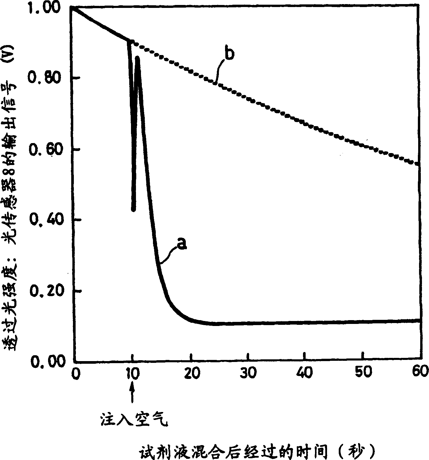
[0061] At this time, if the test solution is mixed with the sulfosalicylic acid reagent solution, the protein components in the test solution will coagulate, and the test solution will be completely turbid. Therefore, the protein concentration can be determined by measuring the degree of turbidity, that is, turbidity. . Here, the turbidity is measured as transmitted light intensity, that is, an output signal of the optical sensor 8 . The higher the protein concentration and the higher the turbidity, the smaller the output signal of the light sensor 8 . In the present embodiment, unlike the first embodiment, not only the diffusion state of...
Embodiment approach 3
[0070] In Embodiment 3, the details of using Image 6 Condition of the sample cell shown. in addition, Figure 7 yes Image 6 A schematic top view of the skeleton portion 14 of the sample cell is shown.
[0071] Image 6 Among them, symbols 2, 6, 7, 8, 9, 10, 12 and 13 represent the same as in Embodiment 1 figure 1 Symbols 2, 6, 7, 8, 9, 10, 12 and 13 have the same constituent elements.
[0072] Image 6 The skeleton portion 14 of the sample cell of the present invention shown is the cuboid aluminum container that the top has the opening 15 that is funnel-shaped opening, and the glass plate (not shown) as optical window is embedded in the two ends of optical path, in Light can pass through the test solution while the test solution is kept.
[0073] For example, the distance in the light propagation direction of the container, that is, the distance between the optical windows is 10 mm, and the distance in the direction perpendicular to the light propagation direction is ...
PUM
 Abstract
Description
Claims
Application Information
 - R&D
- Intellectual Property
- Life Sciences
- Materials
- Tech Scout
- Unparalleled Data Quality
- Higher Quality Content
- 60% Fewer Hallucinations
Browse by: Latest US Patents, China's latest patents, Technical Efficacy Thesaurus, Application Domain, Technology Topic, Popular Technical Reports.
© 2025 PatSnap. All rights reserved.Legal|Privacy policy|Modern Slavery Act Transparency Statement|Sitemap|About US| Contact US: help@patsnap.com