
Optical read-write head driving device

A drive device, read-write head technology, applied in the direction of head configuration/installation, support head, etc., can solve the problems of affecting the stability of the optical drive, high manufacturing process requirements, cost increase, etc., to achieve material saving, easy assembly and use, The effect of saving installation

Inactive Publication Date: 2006-06-21
CHANGZHOU SHINCO AUTOMOTIVE ELECTRONICS
View PDF1 Cites 0 Cited by
  • Summary
  • Abstract
  • Description
  • Claims
  • Application Information

AI Technical Summary

Problems solved by technology

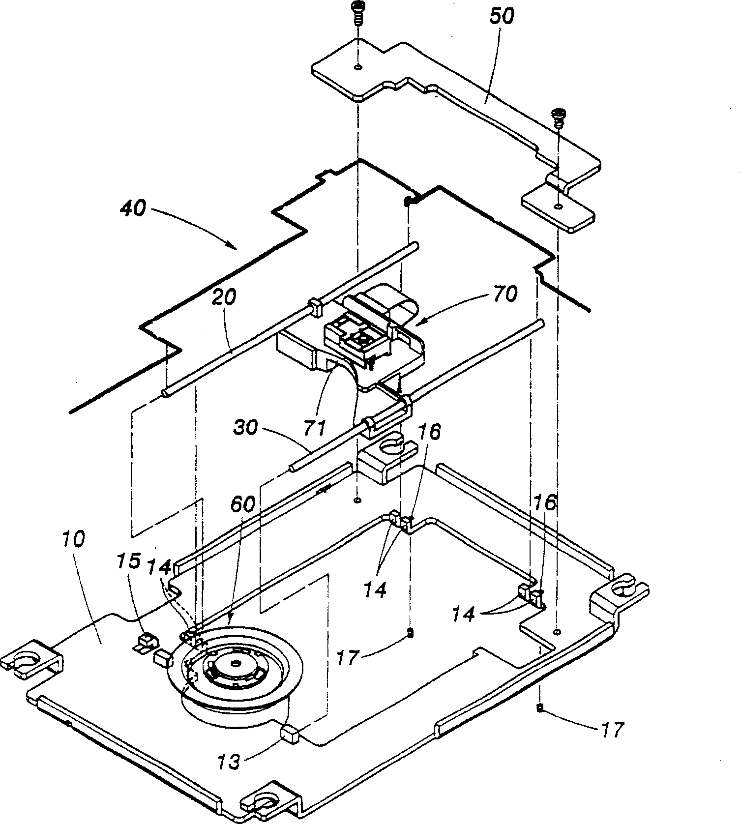
Only the inclination angle of the motion locus plane of the optical pick-up head can be adjusted to make it parallel to the information plane of the optical disc by the adjusting device, but the distance between the motion locus plane of the optical pick-up head and the information plane of the disc cannot be adjusted, so the distance The precision just depends on the manufacturing precision of fixed seat 13, in order to accurately control the distance between the motion track surface of the optical read-write head and the information surface of the optical disc, the manufacturing precision of its fixed seat 13 must be improved, so its manufacturing process requirements Higher, resulting in increased cost
At the same time, when the spindle motor of the rotating moving part drives the disc to run at high speed, it will generate vibration, which will affect the stability of the drive.

Method used


Image

  • Optical read-write head driving device
  • Optical read-write head driving device
  • Optical read-write head driving device

Examples


Embodiment 1

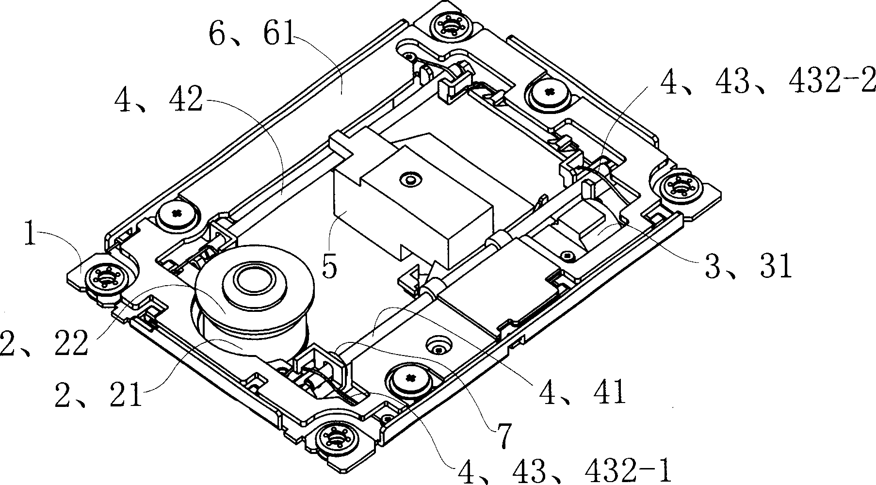
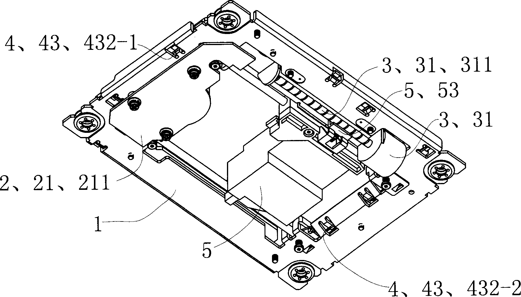
[0030] See Figure 2 to Figure 5 , The optical read-write head driving device of this embodiment has a base plate 1, a rotary motion part 2, a sliding transmission part 3, a guide rod assembly 4, an optical read-write head assembly 5, a sub-base plate assembly 6 and a protection pad 7.

[0031] See Figure 6 and Figure 7 , the rotary moving part 2 has a spindle motor 21 and a turntable 22 connected to the shaft of the spindle motor 21 . The rotary movement part 2 is provided on the front side of the base plate 1 . The rotary moving part 2 is fixed on the bottom plate 1 through the motor plate 211 of the main shaft motor 21 itself, and the main shaft motor 21 of the rotary moving part 2 is a brushless motor.

[0032] See Figure 8 to Figure 10 , the slide transmission part 3 has a slide motor 31 . The sliding transmission part 3 is arranged on the right side of the bottom plate 1 . The coasting transmission part 3 has a coasting motor 31 and a power output. The sliding ...


PUM


Abstract

The invention discloses a driving device of optical reading head, which comprises the following parts: bottom, rotary mobile part, sliding driving part, guide rod component and optical reading head component, wherein the guide rod component possesses right guide rod, left guide rod and guide rod adjustment component; the guide rod adjustment component contains four guide rod seats, elastic location bodies and four adjustment screws; the guide rod seat is fixed on the bottom or the guide rod seat is part of the bottom; two ends of right and left guide rod are set in the corresponding guide rod seat, which are located on the bottom through elastic location body and adjustment screw; the adjustment screw is rotated to adjust the corresponding bottom position of guide rod; four-point type moving track incidence of optical reading head can locate the distance of optical reading head track face and disk information face accurately, which is fit for kinds of precision CD-ROM drive.

Description

technical field [0001] The invention relates to a component of an optical disc drive. Background technique [0002] An optical disc drive (abbreviated as an optical drive) is a device that can read data stored on an optical disc, and an optical disc refers to an information recording medium that uses optical methods to read data through the principles of light reflection, refraction, and polarization. With the continuous development of science and technology, optical drives have been widely used in computers or audio-visual devices. Computers or audio-visual devices can read data recorded in optical discs through optical drives, and can also write data to be stored in optical drives with recording functions. An optical drive with a recording function reads data in the optical disc or writes data in the optical disc through its optical read-write head. The reading method is to use the laser emitted by the optical read-write head to focus on the surface of the optical disc (t...

Claims


Application Information

Patent Timeline
Patent Type & Authority Applications(China)
IPC IPC(8): G11B7/08G11B21/24
Inventor 谢洪涛谈捷嵇一平
Owner CHANGZHOU SHINCO AUTOMOTIVE ELECTRONICS
Learn More