Digital controlled tracing welding machine tool

A welding machine tool and trajectory technology, applied in welding equipment, welding equipment, auxiliary welding equipment, etc., can solve problems such as complex systems, expensive products, and complicated operations, and achieve the effects of accelerated progress and development, reliable performance, and improved quality

Inactive Publication Date: 2006-06-28
夏士林
View PDF1 Cites 3 Cited by
  • Summary
  • Abstract
  • Description
  • Claims
  • Application Information

AI Technical Summary

Problems solved by technology

Its shortcoming is: the whole system is very complicated, need to carry on the programming control to PLC, the product price is expensive and the operation is complicated

Method used


Image

  • Digital controlled tracing welding machine tool
  • Digital controlled tracing welding machine tool
  • Digital controlled tracing welding machine tool

Examples


Embodiment Construction

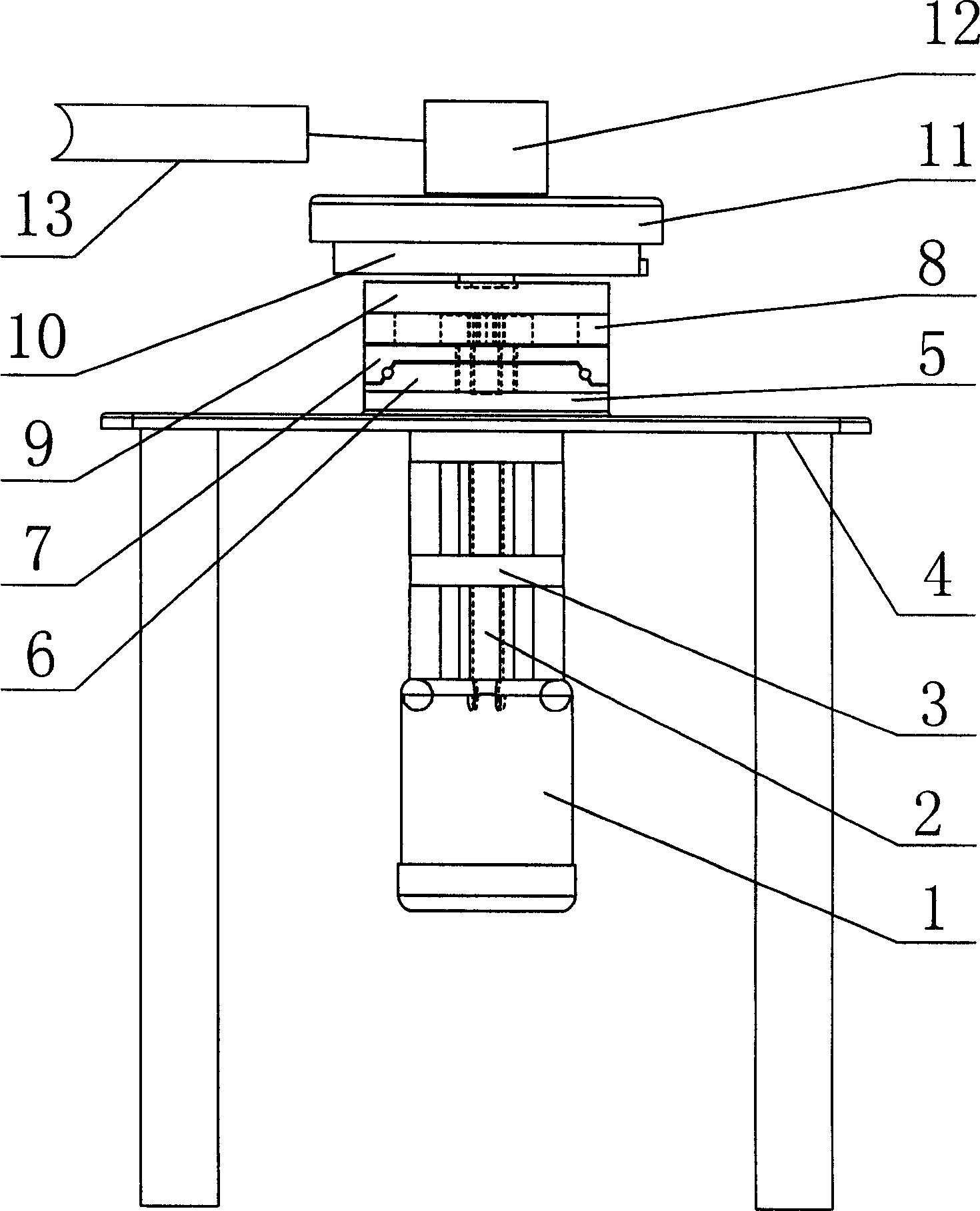
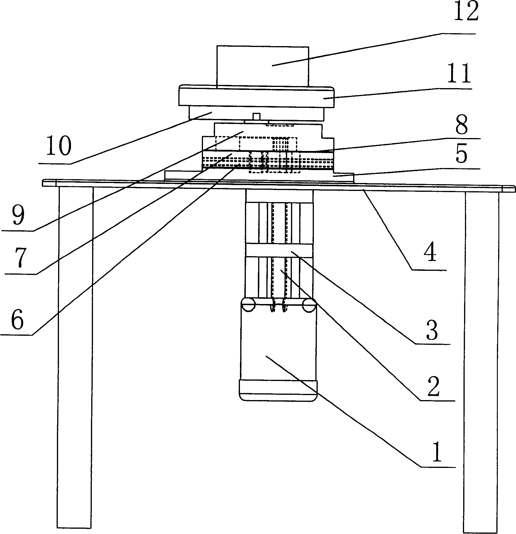
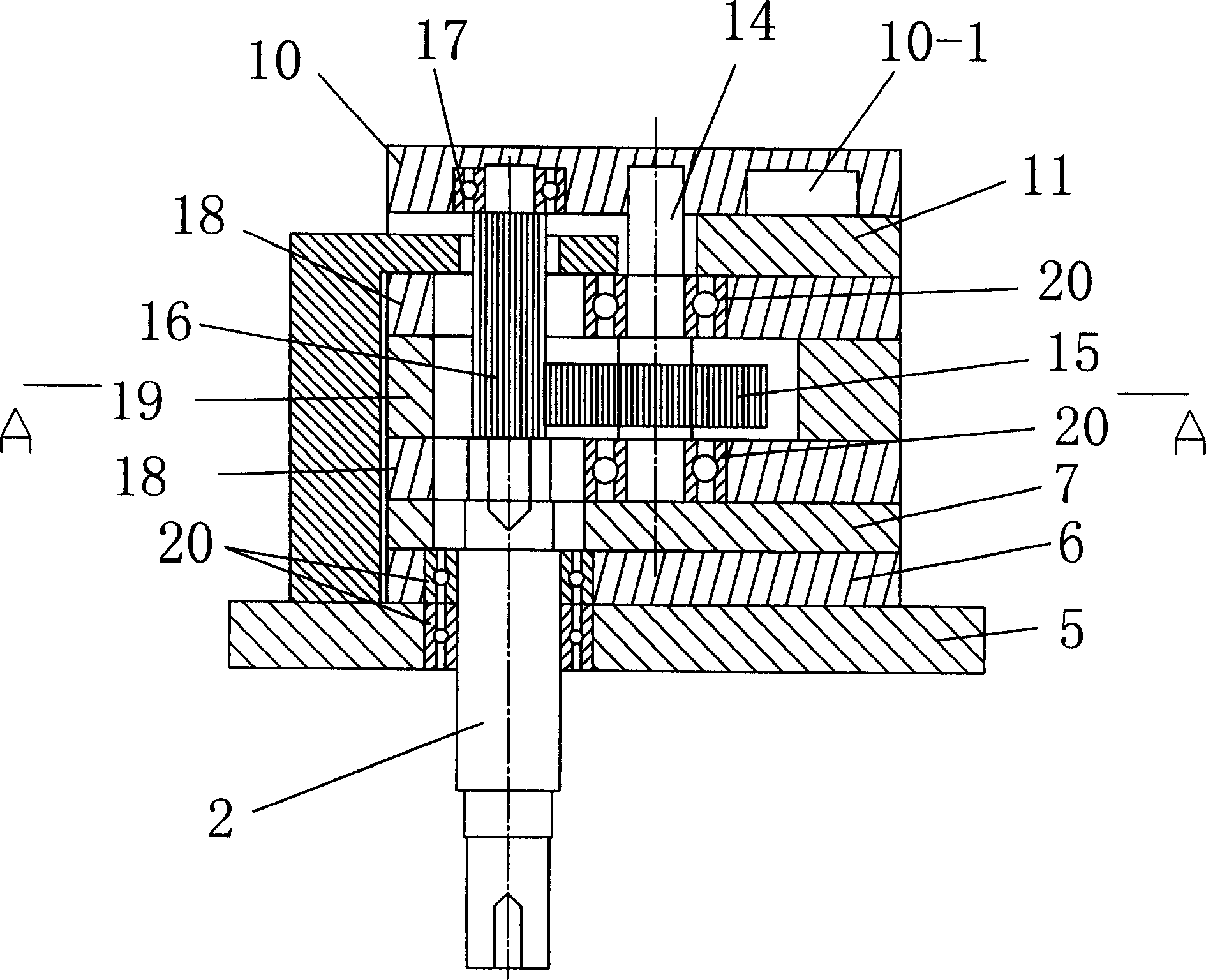
[0027] The present invention will be described in further detail below in conjunction with the accompanying drawings and embodiments.

[0028] As shown in the figure, this CNC trajectory welding machine mainly includes a welding torch 13, a mechanical main frame 4 and fixtures, and a special-shaped welding workpiece 12 is fixedly connected to the worktable 11 through the fixtures. The bottom plate 5 is fixedly connected to the mechanical main frame 4, the bottom plate 5 is fixedly connected with the lower guide rail plate 6, and the lower guide rail plate 6 is provided with an upper guide rail plate 7 which is slidingly matched with it, between the lower guide rail plate 6 and the upper guide rail plate 7 A ball guide groove 21 is provided, in which a group of balls are placed so that the two form rolling friction. The upper guide rail plate 7 is sequentially connected with a gear case plate 8, a bearing fixing plate 9, a trajectory guide plate 10 and a worktable plate 11 and ...


PUM


Abstract

A numerally controlled trace welding machine for welding shaped workpiece is composed of machine frame, welding gun, fixture, upper and lower track plates, trace guiding plate with trace guide slot, bench, speed controllable motor, mainshaft, secondary axle, etc.

Description

technical field [0001] The invention relates to the field of welding equipment, and mainly relates to a numerical control track welding machine tool. Background technique [0002] Welding of profiles with special-shaped cross-sections is a difficult problem to solve. Therefore, many parts composed of profiles with special-shaped cross-sections are generally assembled by screw joints and other easy-to-achieve screw joints. The products produced in this way are not only structurally difficult To adapt to the higher requirements of modern facilities, and the production efficiency is low, product quality is prone to problems, and product consistency is not good. Chinese utility model patent CN2489913Y, patent number: ZL01245236 discloses a welding machine for special-shaped cross-section profiles. A bracket is connected to the main body, and the feeding device connected to the bracket is installed on the main body. The main body is also equipped with a clamping mechanism. And t...

Claims


Application Information

Patent Timeline
Patent Type & Authority Applications(China)
IPC IPC(8): B23K37/047B23K9/12
Inventor 夏士林
Owner 夏士林
Why Eureka
Try Eureka