Hydraulic controllable sluice valve

A gate valve and hydraulic technology, applied in the direction of sliding valve, valve detail, valve device, etc., can solve the problems that the valve cannot meet the requirements, high labor intensity and low efficiency, and achieve the effect of easy automatic control, reduced labor intensity and high efficiency.

Inactive Publication Date: 2006-06-28
TAIYUAN UNIV OF TECH
View PDF0 Cites 11 Cited by
  • Summary
  • Abstract
  • Description
  • Claims
  • Application Information

AI Technical Summary

Problems solved by technology

This kind of valve is not only labor-intensive, but also low in efficiency, which is even more insufficient in multi-pump station water rooms.
In the automatic drainage project, each actuator requires centralized control and automatic operation, and this kind of valve obviously cannot meet the requirements

Method used


Image

  • Hydraulic controllable sluice valve
  • Hydraulic controllable sluice valve

Examples


Embodiment Construction

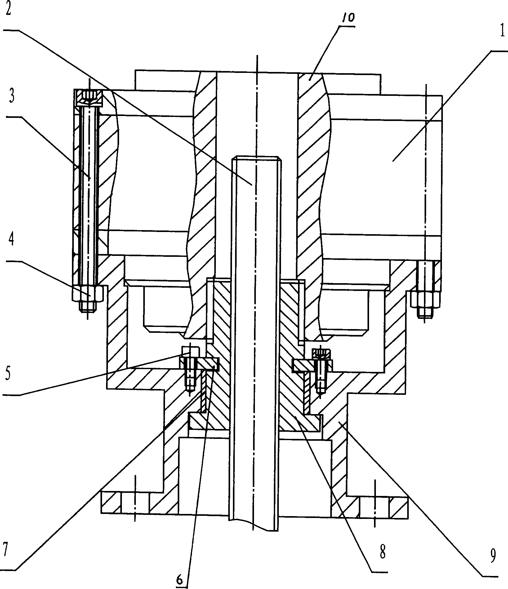
[0011] The bottom of the connecting frame 9 is connected with the valve body by bolts, and the leading screw 2 passes through its central hole and is screwed with the drive nut 8 . The drive nut 8 is in plane contact with the connecting frame 9 . The collar 6 is semicircular, and the longitudinal section of the drive nut 8 is T-shaped. The drive nut 8 is axially positioned by two collars 6 , the drive nut 8 and the copper sleeve 7 are in clearance fit, and the copper sleeve 7 and the connecting frame 9 are in tight fit. The transmission nut 8 is connected with the output shaft 10 of the hydraulic motor through a spline, and the hydraulic motor 1 is fixed on the connecting frame 9 through the bolt 3 and the nut 4 .

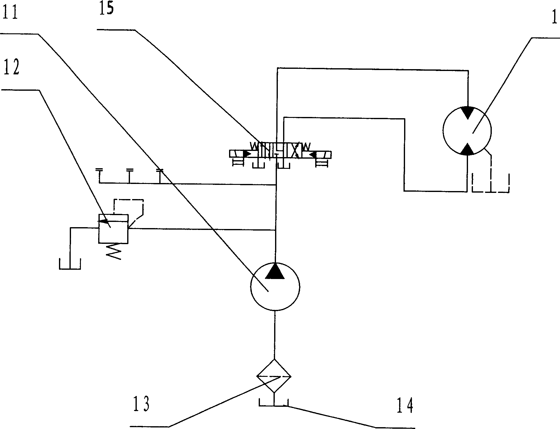
[0012] The hydraulic motor 1 adopts a low-speed high-torque hydraulic motor. The hydraulic pump 11 is a one-way pump, and multiple solenoid valves can be connected in parallel at the outlet of the hydraulic pump 11 to control multiple gate valves, and the paralle...


PUM


Abstract

The invention is a hydraulic controllable gate valve, belonging to a hydraulic driven gate valve, applied to water feeding and discharging engineering and comprising a main body and an auxiliary hydraulic pumping station; the main body comprises valve body, hydraulic motor, connection frame, drive nut, screw rod, clamp ring and copper cover; the hydraulic motor is connected with the drive nut through spline, the drive nut is axially located through the clamp ring and connection frame, and the hydraulic motor and the clamp ring are both fixed on the connection frame; the screw rod is connected with the drive nut through spiral auxiliary; the auxiliary hydraulic pump station comprises oil tank, hydraulic pump, electromagnetic directional valve and overflow valve; the inlet of the hydraulic pump is connected with the oil tank and its outlet is connected with the mouth P of the electromagnetic directional valve, the hydraulic motor is connected with mouths A and B of the electromagnetic directional valve, and the overflow valve is connected with the outlet end of the hydraulic pump.

Description

technical field [0001] The present invention relates to a hydraulically driven gate valve. Background technique [0002] Now the commonly used gate valve adopts the screw nut transmission mode, the nut rotates, and through the screw pair, it is converted into the linear motion of the screw, which drives the wedge gate to move up and down, so as to control the opening and closing of the valve. Due to the low transmission efficiency of the lead screw and nut, the operating torque is large, especially when opening, there is a large pressure difference on both sides of the valve plate, and the starting torque is twice the operating torque. With the increase of gate valve diameter and water pump head, the starting torque and running torque are getting bigger and bigger. When a high-lift pumping station is running, it often requires two people to turn the handwheel at the same time to operate. This kind of valve is not only labor-intensive, but also low in efficiency, which is ev...

Claims


Application Information

Patent Timeline
Patent Type & Authority Applications(China)
IPC IPC(8): F16K3/00F16K31/16
Inventor 寇子明吴娟郝建功高贵军李泽松
Owner TAIYUAN UNIV OF TECH
Why Eureka
Try Eureka