
Scanning micro-mirror package, method for fabricating the same, and optical scanning device employing the same

A scanning micromirror and micromirror technology, applied in the manufacture of microstructure devices, optics, optical components, etc., can solve the problems of insufficient high-resolution displays

Inactive Publication Date: 2006-06-28
LG ELECTRONICS INC
View PDF0 Cites 6 Cited by
  • Summary
  • Abstract
  • Description
  • Claims
  • Application Information

AI Technical Summary

Problems solved by technology

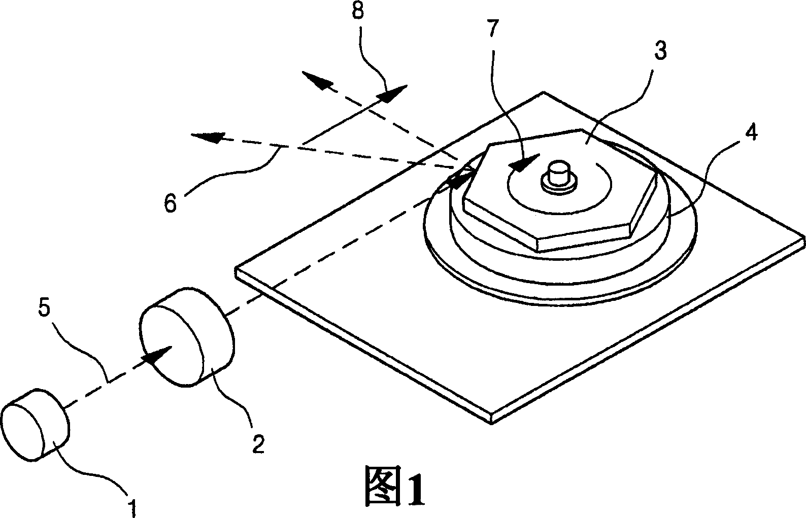
[0010] Scanning devices using polygonal mirrors 3 are not sufficient for high resolution displays as they are only capable of scanning in a single direction at relatively high speeds

Method used


Image

  • Scanning micro-mirror package, method for fabricating the same, and optical scanning device employing the same
  • Scanning micro-mirror package, method for fabricating the same, and optical scanning device employing the same
  • Scanning micro-mirror package, method for fabricating the same, and optical scanning device employing the same

Examples


Embodiment Construction

[0070] Reference will now be made in detail to preferred embodiments of the present invention, examples of which are illustrated in the accompanying drawings, wherein like reference numerals refer to like parts throughout. In the following embodiments, descriptions of well-known functions and structures are omitted if they obscure the gist of the present invention. The following embodiments are described in order to explain the present invention by referring to the figures.

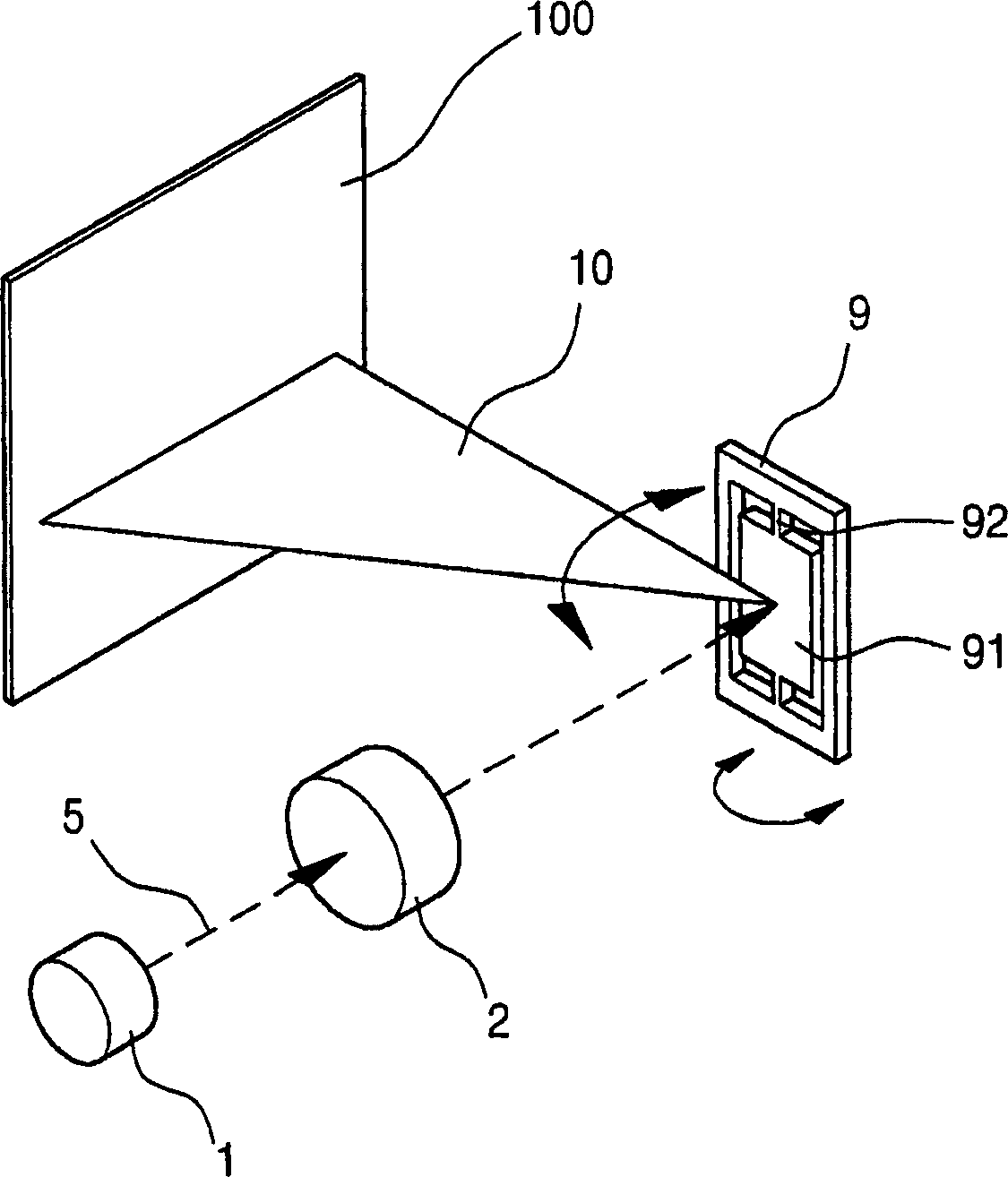
[0071] refer to figure 2 , showing a one-dimensional (line) scanning system including scanning micromirrors in perspective view.

[0072] Such as figure 2 As shown, the scanning micromirror 9 has such a structure that the reflective surface 91 is supported on the torsion arm 92, and the torsion arm 92 serves as a pivot and restores the torque of the reflective surface 91 as much as possible based on the operation. In this structure, according to the input signal, the reflective surface 91 can perform b...


PUM


Abstract

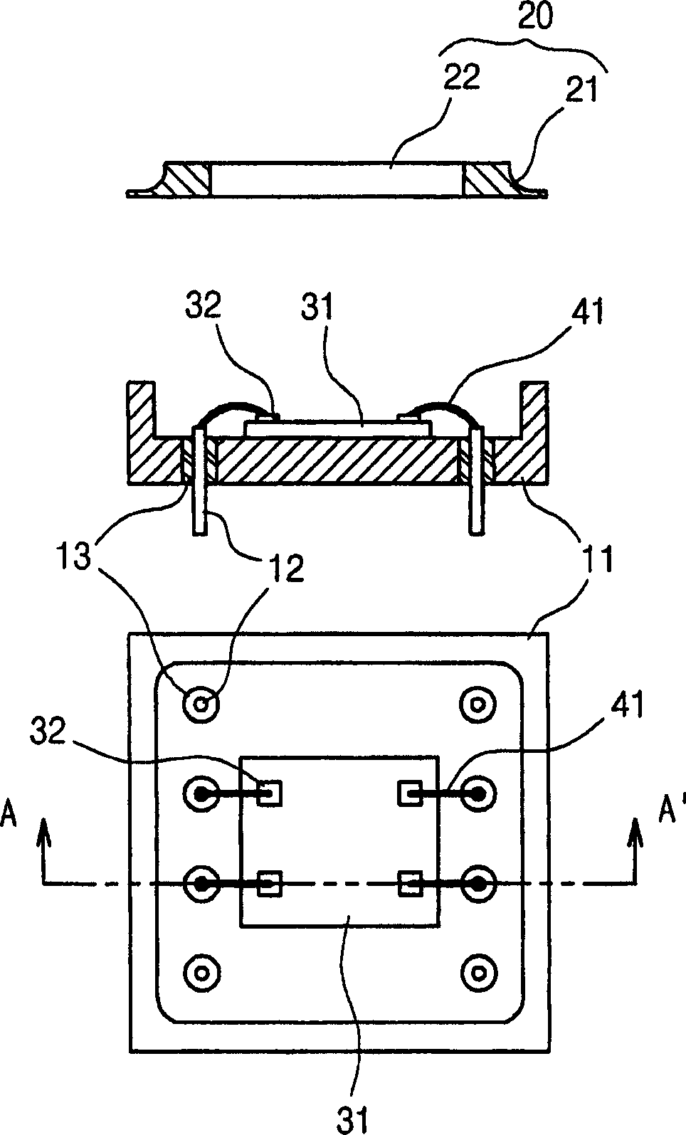
The invention discloses a scanning micromirror package used in an optical scanning device, wherein the micromirror reflects an incident light beam and modulates an optical path of the reflected light beam in response to an input signal, and a manufacturing method thereof. The scanning micromirror package comprises a suitable cover with a transparent window through which the light beam passes, and a housing combined with the cover, in which the micromirror is protected from external influences and enables it to perform its own function well. The scanning micromirror package can be applied to a device that displays and reads image information or data by scanning a light beam emitted from a light source over a predetermined range. With such a structure, the scanning micromirror package allows the micromirror to optimally exhibit its optical and mechanical properties in addition to protecting the micromirror from external factors that negatively affect performance. Furthermore, in addition to reducing product cost, the scanning micromirror package of the present invention can be manufactured in a slim and lightweight form, and can be applied to scanning systems using various types of micromirrors.

Description

technical field [0001] The present invention relates to a scanning micromirror package for use in an optical scanning device and a method of manufacturing the same, wherein the micromirror reflects an incident light beam and modulates the optical path of the reflected light beam in response to an input signal. [0002] The package and method according to the present invention can be applied to devices that display and read image information or data by scanning a light beam emitted from a light source over a predetermined range, such as laser printers, confocal microscopes, barcode scanners, scanning displays, sensors, etc. . Furthermore, the invention can be applied to switching devices as well as scanning devices. Background technique [0003] With the development of optical devices in recent years, various technologies using light as a medium for inputting and outputting various information and for information transmission have arisen. Among them, there are methods of sc...

Claims


Application Information

Patent Timeline
Patent Type & Authority Applications(China)
IPC IPC(8): G02B26/12
CPCG02B26/0833G02B26/105H01L2224/48091H01L2924/16151H01L2924/16195H01L2924/00014B81C1/00142G02B1/11G02B7/1815B81C2203/0145
Inventor 李泳柱李时衡池昌炫
Owner LG ELECTRONICS INC
Learn More