
Am/fm radio receiver and local oscillator circuit used therein

一种无线电接收机、局部振荡的技术,应用在局部振荡电路领域,能够解决触发器段数增加、锁相时间拉长、易恶化等问题

Inactive Publication Date: 2006-06-28
RICOH KK +1
View PDF2 Cites 1 Cited by
  • Summary
  • Abstract
  • Description
  • Claims
  • Application Information

AI Technical Summary

Problems solved by technology

[0021] 1. The number of flip-flop segments constituting the programmable counter 17 will increase, resulting in larger circuit scale
[0022] 2. The phase lock time (lockup time) of the PLL circuit will be lengthened
[0023] 3. The S / N ratio will easily deteriorate

Method used


Image

  • Am/fm radio receiver and local oscillator circuit used therein
  • Am/fm radio receiver and local oscillator circuit used therein
  • Am/fm radio receiver and local oscillator circuit used therein

Examples


Embodiment Construction

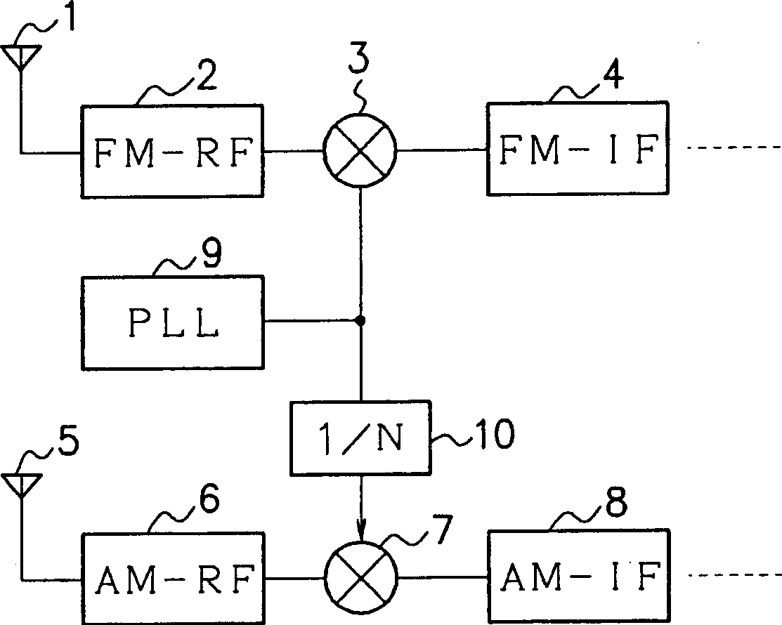
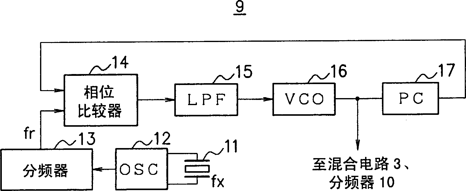
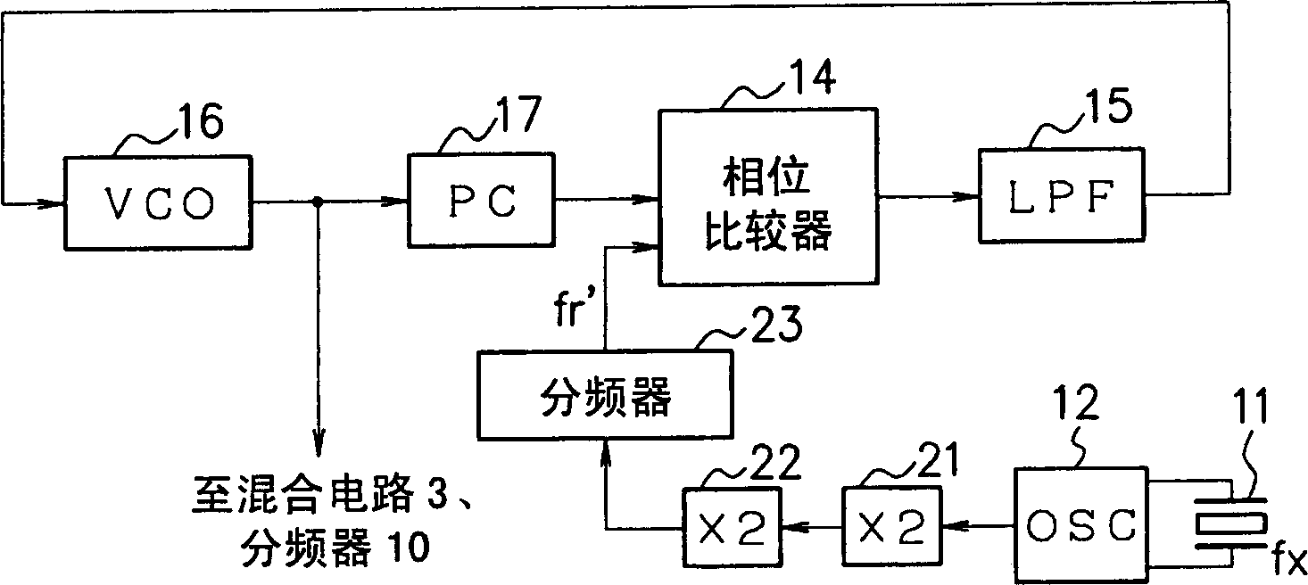
[0046] Hereinafter, an embodiment of the present invention will be described with reference to the drawings. image 3 Shown is a configuration example of a local oscillation circuit (PLL circuit) of the present embodiment. Also, here image 3 in, with figure 2 The same symbols shown have the same functions, and will not be repeated here. Additionally, using this image 3 An AM / FM radio receiver construction with the PLL circuit shown, such as figure 1 shown.

[0047] Such as image 3 As shown, the PLL circuit of this embodiment includes: a crystal oscillator 11, a reference oscillator (OSC) 12, a frequency divider 23, a phase comparator 14, a low-pass filter (LPF) 15, a voltage controlled oscillator ( VCO) 16, programmable counter (PC) 17, and 2-stage frequency multiplication circuits 21, 22.

[0048] The 2-stage frequency multiplication circuit 21, 22 is to amplify the frequency of the reference oscillation signal output from the reference oscillator 12 by 2 2 times....


PUM


Abstract

By setting the frequency of the reference oscillating signal output from the reference oscillator (12) and performing the frequency doubling circuit (21, 22), the frequency fx=75KHz of the crystal oscillator (11) can be quadrupled. The frequency of the reference oscillating signal (300KHz), and the frequency assigned by the average 1 channel of AM radio broadcast, multiplied by the frequency (54KHz) of the specified frequency division ratio, is the frequency of the reference oscillating signal, which becomes larger than the previous situation. As a result, the frequency division ratio of the programmable counter (17) can be reduced, and the effects of reducing the circuit scale, shortening the phase-locking time, and improving the S / N ratio can be achieved.

Description

technical field [0001] The present invention relates to an AM / FM radio receiver and a local oscillating circuit using it, in particular to a frequency synthesizer (frequency synthesizer) suitable for use in a PLL (Phase Locked Loop) circuit, which can produce AM and FM broadcasting. AM / FM radio receivers for local oscillator signals. Background technique [0002] The reception mode of commercially available radio receivers today is superheterodyne (superheterodyne) as the mainstream. The superheterodyne method converts the frequency of the desired broadcast frequency to the center frequency of the intermediate frequency bandpass filter without changing the center frequency and band characteristics of the intermediate frequency bandpass filter. , to only pull out the signal for this broadcast frequency. Frequency conversion is implemented by mixing the received signal amplified by high frequency and the frequency local oscillation signal corresponding to the channel selecti...

Claims


Application Information

Patent Timeline
Patent Type & Authority Applications(China)
IPC IPC(8): H03L7/18H03J5/02H03J5/24H03L7/07H03L7/181H04B1/26
CPCH03J5/0245H03J5/242H03J2200/10H03L7/07H03L7/181H03L7/18H04B1/26
Inventor 池田毅宫城弘
Owner RICOH KK
Learn More