Radio frequency signal source capable of reducing output signal stray

A technology of radio frequency signal source and output signal, applied in the field of radio frequency signal source, can solve the problem of poor isolation of the phase-locked frequency conversion unit 102, etc., achieve the effect of reducing phase noise, improving performance indicators, and reducing stray signals

Inactive Publication Date: 2015-04-29
SUZHOU RIGOL PRECISION ELECTRIC TECH
View PDF5 Cites 3 Cited by
  • Summary
  • Abstract
  • Description
  • Claims
  • Application Information

AI Technical Summary

Problems solved by technology

[0005] The radio frequency signal source 100 in the prior art has a problem: when outputting an output signal in the frequency range of 8 kHz to 30 MHz, the DDS signal is switched to the direct path 32 through the switch 104, and the phase detector 24 of the phase-locked frequency conversion unit 102 has no reference signal Input, the PLL module formed by the phase detector 24, the loop filter 25, the tunable oscillator 26 and the N frequency divider 27 is in an out-of-lock state, even if the switching selection of the switch 104 does not input the DDS signal to the phase-locked frequency conversion Unit 102, because the isolation of the phase-locked frequency conversion unit 102 is not good, through space coupling and channel transmission, part of the DDS signal will also be output at the output terminal 34 through the phase-locked frequency conversion unit 102, so that the output terminal 34 can output the first 8kHz-30MHz In addition to a frequency band signal, there is also a spurious signal brought by a phase-locked frequency conversion unit 102

Method used


Image

  • Radio frequency signal source capable of reducing output signal stray
  • Radio frequency signal source capable of reducing output signal stray
  • Radio frequency signal source capable of reducing output signal stray

Examples


Embodiment Construction

[0052] In order to make the above objects, features and advantages of the present invention more comprehensible, the present invention will be further described in detail below in conjunction with the accompanying drawings and specific embodiments.

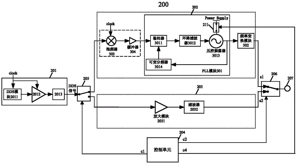
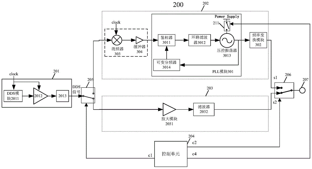
[0053] refer to figure 2 , shows a schematic structural diagram of Embodiment 1 of a radio frequency signal source 200 for reducing spurious output signals according to the present invention. The radio frequency signal source 200 includes:

[0054] The DDS source unit 201 is used to perform direct digital frequency synthesis processing according to the clock signal clock to generate a DDS signal;

[0055] The phase-locked frequency conversion unit 202 includes a voltage-controlled oscillator 3013, a power supply Power Supply for supplying power to the voltage-controlled oscillator, and a fourth switch 211 arranged between the voltage-controlled oscillator 3013 and the power supply Power Supply, the phase-locked frequency conversi...


PUM


Abstract

The invention provides a radio frequency signal source capable of reducing output signal stray. The radio frequency signal source comprises a DDS (direct digital synthesizer) signal source unit, a phase-locked frequency conversion unit, a through path, a control unit, a first switch and a second switch, wherein the control unit is used for generating a fourth control signal; the phase-locked frequency conversion unit comprises a fourth switch arranged between a voltage-controlled oscillator and a power supply; the fourth switch is switched on according to the fourth control signal when the first switch selects to input a DDS signal into the phase-locked frequency conversion unit so as to enable the power supply to supply power to the voltage-controlled oscillator and is switched off according to the fourth control signal when the first switch selects to input the DDS signal into the through path so as to enable the power supply not to supply power to the voltage-controlled oscillator. According to the radio frequency signal source, the power supply is enabled not to supply power to the voltage-controlled oscillator, the amplitude of the DDS signal output from the phase-locked frequency conversion unit to an output port is decreased, stray signals caused by the phase-locked frequency conversion unit are reduced, non-harmonic stray of output signals is reduced, and the spectrum purity of the output signals is increased.

Description

technical field [0001] The invention relates to the technical field of test and measurement, in particular to a radio frequency signal source for reducing spurious output signals. Background technique [0002] The RF signal source is a radio frequency signal transmitting device, which can output a signal with stable frequency and amplitude, which can be used to calibrate the spectrum analyzer, simulate and generate various signals required by the user, etc. [0003] The US Patent No. US8044725 "Signal generator with directly-extractable DDS signal source" discloses a radio frequency signal source. like figure 1 As shown, the radio frequency signal source 100 includes: a direct digital frequency synthesis (DDS or DDFS, Direct Digital Frequency Synthesis) source unit 101, which is used to perform direct digital frequency synthesis and other processing according to a clock signal to generate a DDS signal; a phase-locked frequency conversion unit 102 , used to perform phase-lo...

Claims


Application Information

Patent Timeline
Patent Type & Authority Applications(China)
IPC IPC(8): H03L7/099
Inventor 张弘何毅军王悦王铁军李维森
Owner SUZHOU RIGOL PRECISION ELECTRIC TECH
Why Eureka
Try Eureka