

A. c. electricity control device
A technology of AC voltage and control devices, which is applied in the direction of control/regulation systems, adjustment of electrical variables, conversion equipment that can be converted to DC without intermediate conversion, etc., and can solve problems such as difficult maintenance of supply voltage
- Summary
- Abstract
- Description
- Claims
- Application Information
AI Technical Summary
Problems solved by technology
Method used
Image

Examples
no. 1 Embodiment approach
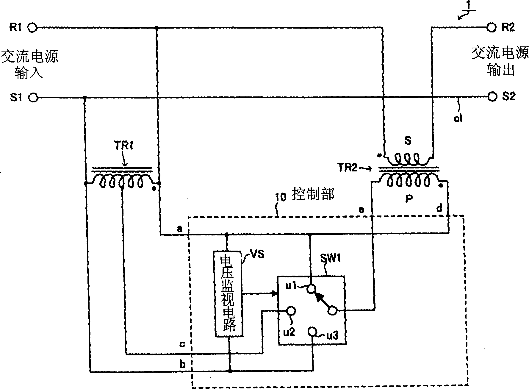
[0063] figure 1 It is a schematic configuration diagram showing the AC voltage control device of the first embodiment. The AC voltage control device 1 includes a pair of input terminals for inputting a single-phase two-wire system AC power supply on the input side, that is, an input terminal R1 and an input terminal S1, and an output terminal including a single-phase two-wire system output voltage that lowers the output voltage. A pair of output terminals, output terminal R2 and output terminal S2.
[0064] The so-called single-phase two-wire system power supply voltage is, for example, a power supply method of a commercial power supply of AC 100 V or AC 200 V that is also used in ordinary households. In this mode, for example, 200V is input to the input terminal R1, and the input terminal S1 is grounded, so an AC power supply voltage of 200V is applied between the input terminals R1-S1.
[0065] exist figure 1 In, the input terminal R1 and the input terminal S1 are connect...
no. 2 Embodiment approach
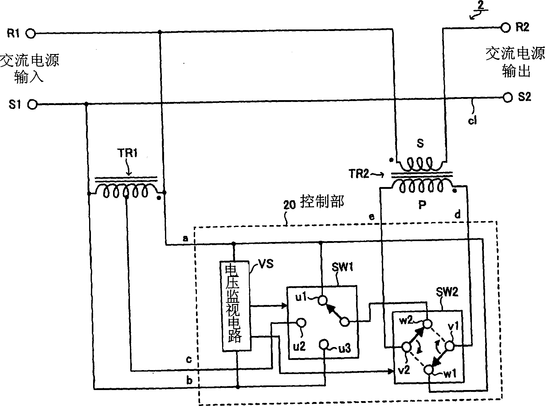
[0087] image 3 It is a schematic configuration diagram showing the structure of the AC voltage control device 2 of the second embodiment. In this AC voltage control device 2 , the control unit 20 is configured by adding a switch SW2 for switching the connection polarity between the primary winding P and the secondary winding S of the transformer TR2 to the control unit 10 of the first embodiment. Also, other constructs with figure 1 The AC voltage control device 1 shown in the first embodiment is the same, and the same reference numerals are assigned to the same parts.
[0088] In the first embodiment, in order to increase the energy-saving effect, the step-down output obtained by reducing the AC power supply voltage is supplied to the load. In addition, in a building where the power condition is not good, there is a problem that the operation of the equipment becomes unstable due to a drop in the supply voltage. In this case, instead, it is necessary to increase the AC po...
no. 3 Embodiment approach
[0108] Figure 5 It is a schematic configuration diagram showing the AC voltage control device 3 of the third embodiment. In this AC voltage control device 3, a switch SW3 is inserted instead of the switches SW1 and SW2 included in the control unit 20 of the second embodiment to form a control unit 30. The switch SW3 switches the primary winding P and the secondary winding of the transformer TR2. The connection polarity of S, and at the same time switch the mutual connection relationship between one end and the other end of the primary winding P and one end, the tap, and the other end of the autotransformer TR1. In addition, other configurations are the same as those of the AC voltage control device 1 shown in the first embodiment, and the same parts are denoted by the same reference numerals.
[0109] exist Figure 5 Among them, one end of the primary winding P of the transformer TR2 is connected to the base point x1 of the switch SW3 through the lead d, and the other end i...
PUM
 Abstract
Description
Claims
Application Information