
Flow control valve with magnetic field sensor

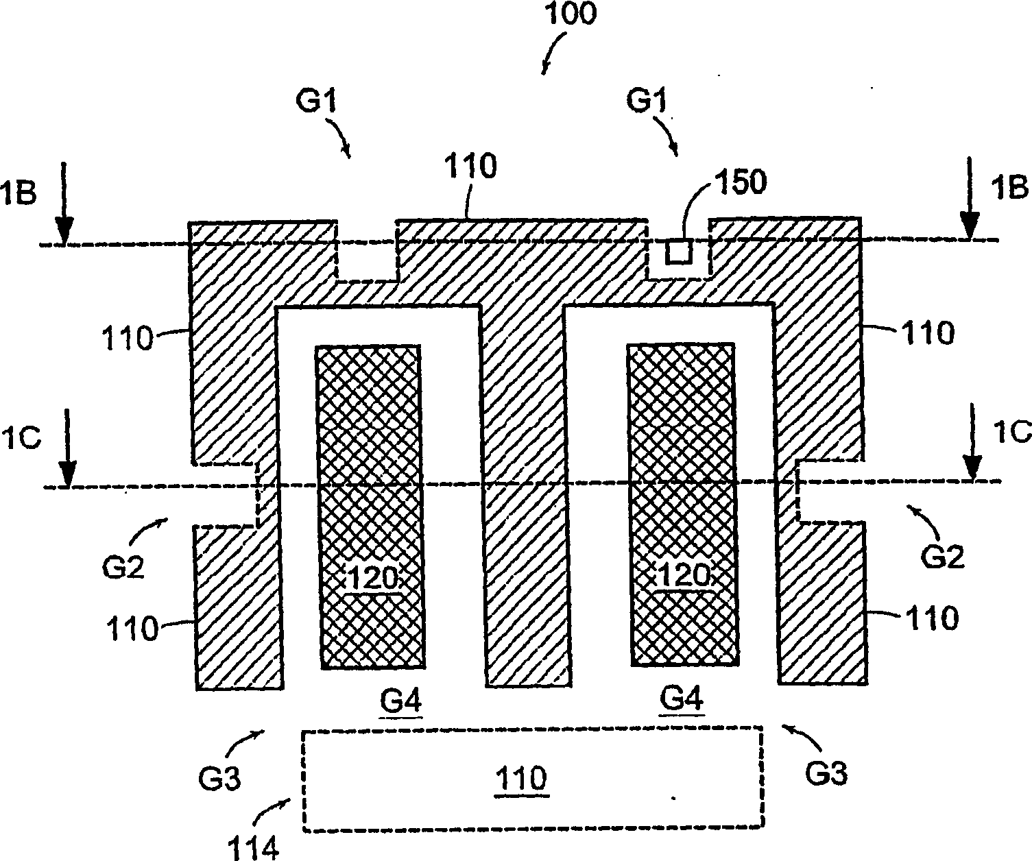
A technology of magnetic flux sensor and magnetic field generator, applied in flow control, non-electric variable control, magnetic variable adjustment, etc., can solve the problem of increasing the cost of flow control equipment, and achieve the effect of alleviating hysteresis and other factors and alleviating the impact

Inactive Publication Date: 2006-07-05
MKS INSTR INC
View PDF0 Cites 10 Cited by
  • Summary
  • Abstract
  • Description
  • Claims
  • Application Information

AI Technical Summary

Problems solved by technology

However, this approach increases the cost of flow control equipment

Method used


Image

  • Flow control valve with magnetic field sensor
  • Flow control valve with magnetic field sensor
  • Flow control valve with magnetic field sensor

Examples


Embodiment Construction

[0029] The word "hysteresis" here means the hysteresis of the magnetization value in a magnetic material due to changing the magnetizing force.

[0030] The word "residue" here means the magnetic induction remaining in a magnetized substance that is no longer under the influence of an external magnetic field. For example, the ferromagnetic plunger of a solenoid may exhibit residual magnetization when no current is applied to the solenoid.

[0031] The word "reluctance" here means the resistance to magnetic flux in a reluctance magnetic circuit and can be defined as the ratio of the magnetic potential difference to the corresponding magnetic flux. The reluctance part of a flux circuit is similar to the resistive part of a current circuit.

[0032] As used herein, "ferromagnetic material" means a material that concentrates magnetic flux by a factor greater than about 10. The relative permeability of ferromagnetic materials can be as high as about 1,000,000 as a ratio to the va...


PUM


Abstract

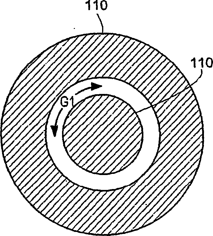
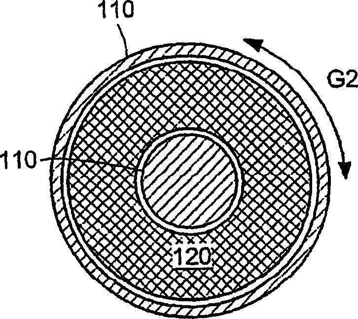
Solenoid devices that include magnetic field sensors and methods for operating the devices are described. A device includes a magnetic field generator that generates a magnetic flux that extends through a magnetic flux circuit member formed at least in part from a ferromagnetic material and defining a gap that is effectively free of any ferromagnetic material. A magnetic flux sensor is disposed to sense a portion of the magnetic flux that extends across the gap. A device can be implemented as a fluid flow control valve.

Description

technical field [0001] This invention relates to solenoid devices, and more particularly to solenoid flow control valves. Background technique [0002] Control and measurement of flowing gases and liquids is important in many industrial manufacturing situations such as semiconductor fabrication, photocoating deposition, and flat panel display fabrication. For example, these applications may require the use of precise quantities of fluids to form films of desired thickness and composition. Mass flow controllers are generally used for fluid flow control and / or measurement in support of process tools used in these applications. [0003] Mass flow controllers generally include a solenoid valve interposed between fluid flow through a valve orifice. A common solenoid valve has an insulated coil wrapped around a plunger core and enclosed in a housing. Applying electrical current to the coil positions the plunger relative to or against the bore in the valve seat to control the fl...

Claims


Application Information

Patent Timeline
IPC IPC(8): G05F7/00H01F7/08H01F7/18
CPCH01F7/081H01F7/1844G05D7/00
Inventor M·M·贝森
Owner MKS INSTR INC
Learn More