
Centrifugal fan for purification treatment

A centrifugal fan and purification treatment technology, which is applied to components, applications, household appliances, etc. of pumping devices for elastic fluids, can solve the problems of reduced purification effect, high processing difficulty, easy to block the purification system, etc., and achieve effective recovery Effect

Inactive Publication Date: 2006-07-12
玉环太平洋机械有限公司
View PDF0 Cites 15 Cited by
  • Summary
  • Abstract
  • Description
  • Claims
  • Application Information

AI Technical Summary

Problems solved by technology

The purification work is basically undertaken by the purifier, especially the waxy dust in the polishing machine industry is relatively difficult to deal with, and the waxy dust is easy to block the purification system, greatly reducing the purification effect

Method used


Image

  • Centrifugal fan for purification treatment
  • Centrifugal fan for purification treatment
  • Centrifugal fan for purification treatment

Examples


Embodiment Construction

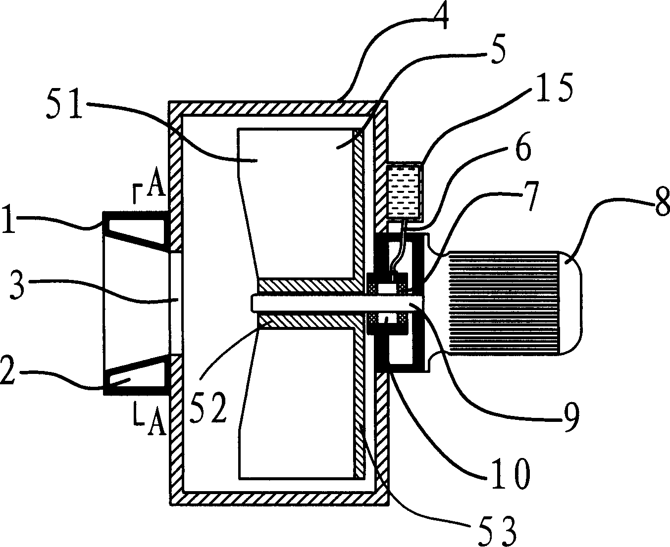
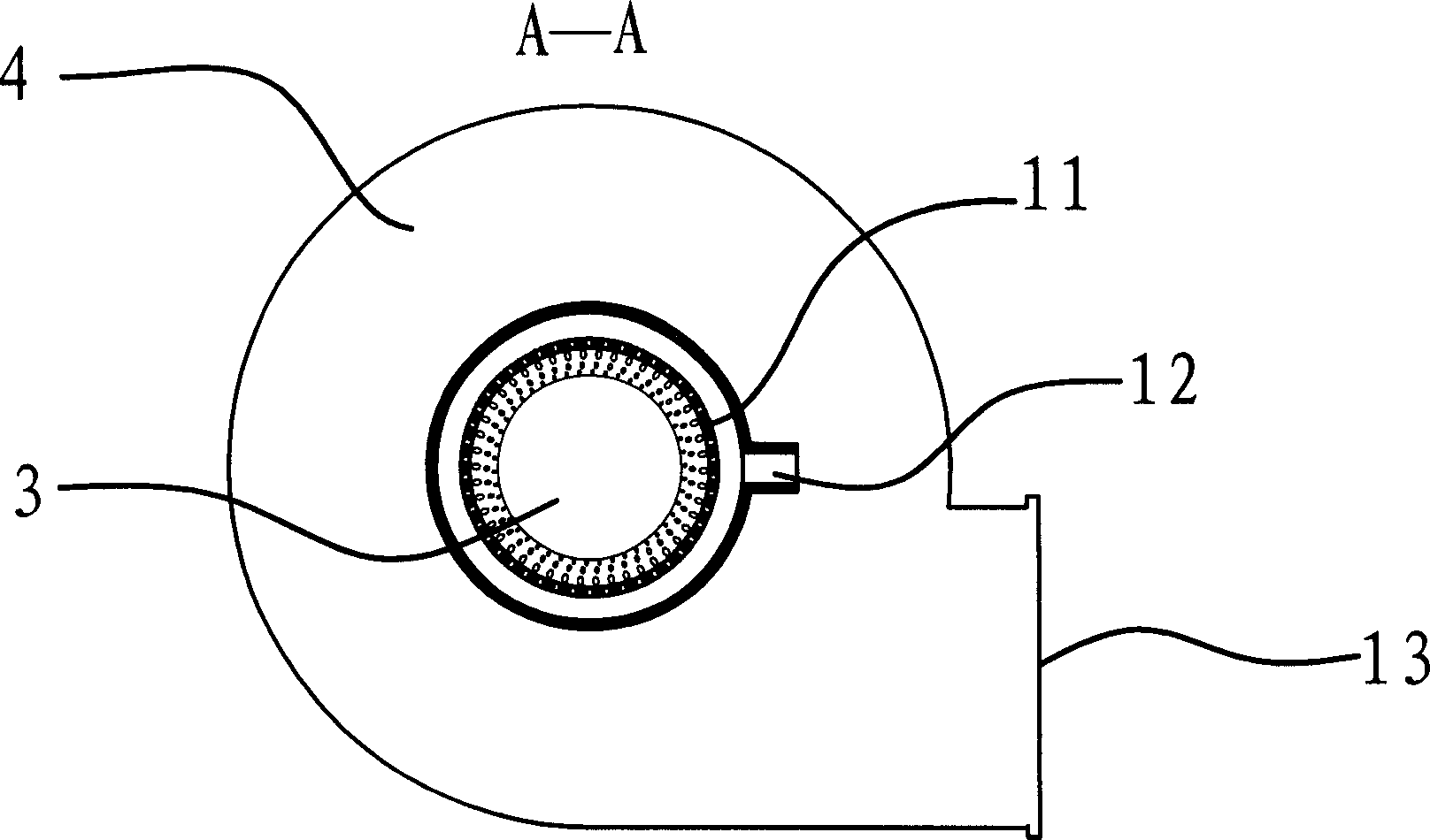
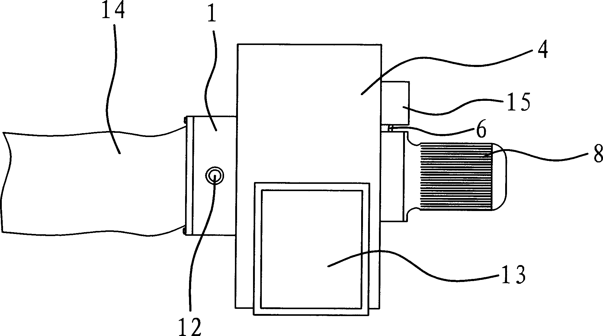
[0016] Such as figure 1 with figure 2 As shown, the centrifugal fan used for purification treatment is mainly composed of a casing 4 , an impeller 5 arranged in the casing 4 , and a motor 8 arranged on the casing 4 . Wherein, the casing 4 is provided with an air inlet 3 and an air outlet 13 , and the air inlet 3 communicates with the air outlet 13 . The impeller 5 is located between the air inlet 3 and the air outlet 13 . The motor 8 is provided with a rotating shaft 9 , which passes through the housing 4 and is connected with the impeller 5 .

[0017] An annular water supply chamber 1 is provided outside the air inlet 3 on the housing 4 , and a chamber 2 is provided in the water supply chamber 1 . The inner surface of the water supply chamber 1 is tapered, and there are several water outlet holes 11 on the inner surface of the water supply chamber 1 facing the direction of the air inlet 3, and the water outlet holes 11 are generally densely distributed in the water supply...


PUM


Abstract

The invention relates to a centrifugal fan for purifying, which comprises a case, a inlet and a outlet on the case, a blade wheel inside the case, and a motor at the outer side of case. Wherein, the motor is connected to the blade wheel via a rotational axle through the case; the inlet or outlet of said case has a water-feeding chamber; the wall of water-feeding chamber that aiming to the inlet or outlet has several water discharging holes; and the wall of water-feeding chamber has a water inlet pipe. The invention can simplify the structure of purifier, reduce producing cost, effectively purify the air with dust and collect the dust.

Description

technical field [0001] The invention relates to a centrifugal fan, in particular to a centrifugal fan used for purification treatment. Background technique [0002] As a ventilation device, the fan has a wide range of uses, both for air exchange and for purification and dust removal. Existing fans used for purification generally adopt centrifugal fans. The structure includes a shell, an impeller inside the shell, and a motor outside the shell. The motor is connected to the impeller through a rotating shaft passing through the shell. The housing is also provided with a connected air inlet and air outlet. The centrifugal fan of this structure is matched with the corresponding air duct during the purification process. The main function is to use the wind pressure and gravity to absorb and convey the dust-laden airflow. The dust-laden airflow passes through the purifier to achieve the purpose of purification, and the centrifugal fan itself has no purification function. , has n...

Claims


Application Information

Patent Timeline
IPC IPC(8): F04D29/70F04D29/42F04D17/08F24F3/16
Inventor 陈美青
Owner 玉环太平洋机械有限公司
Learn More