

Device and method for controllably cooling thick steel plate
A technology for controlling cooling and controlling devices, applied in metal rolling, manufacturing tools, metal rolling, etc., can solve the problems of uneven cooling, difficult production, deformation, etc., and achieve the effect of good material uniformity
- Summary
- Abstract
- Description
- Claims
- Application Information
AI Technical Summary
Problems solved by technology
Method used
Image

Examples
Embodiment 1
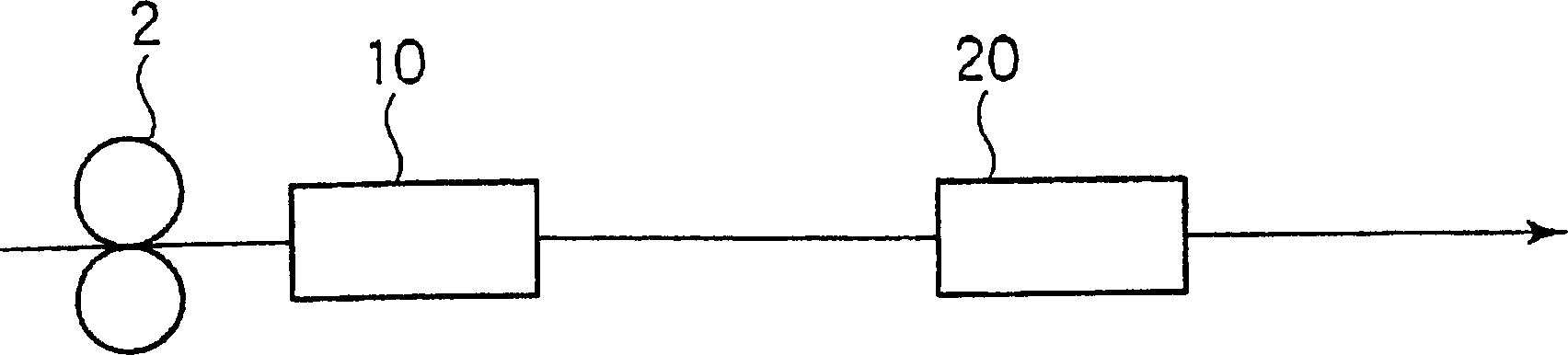
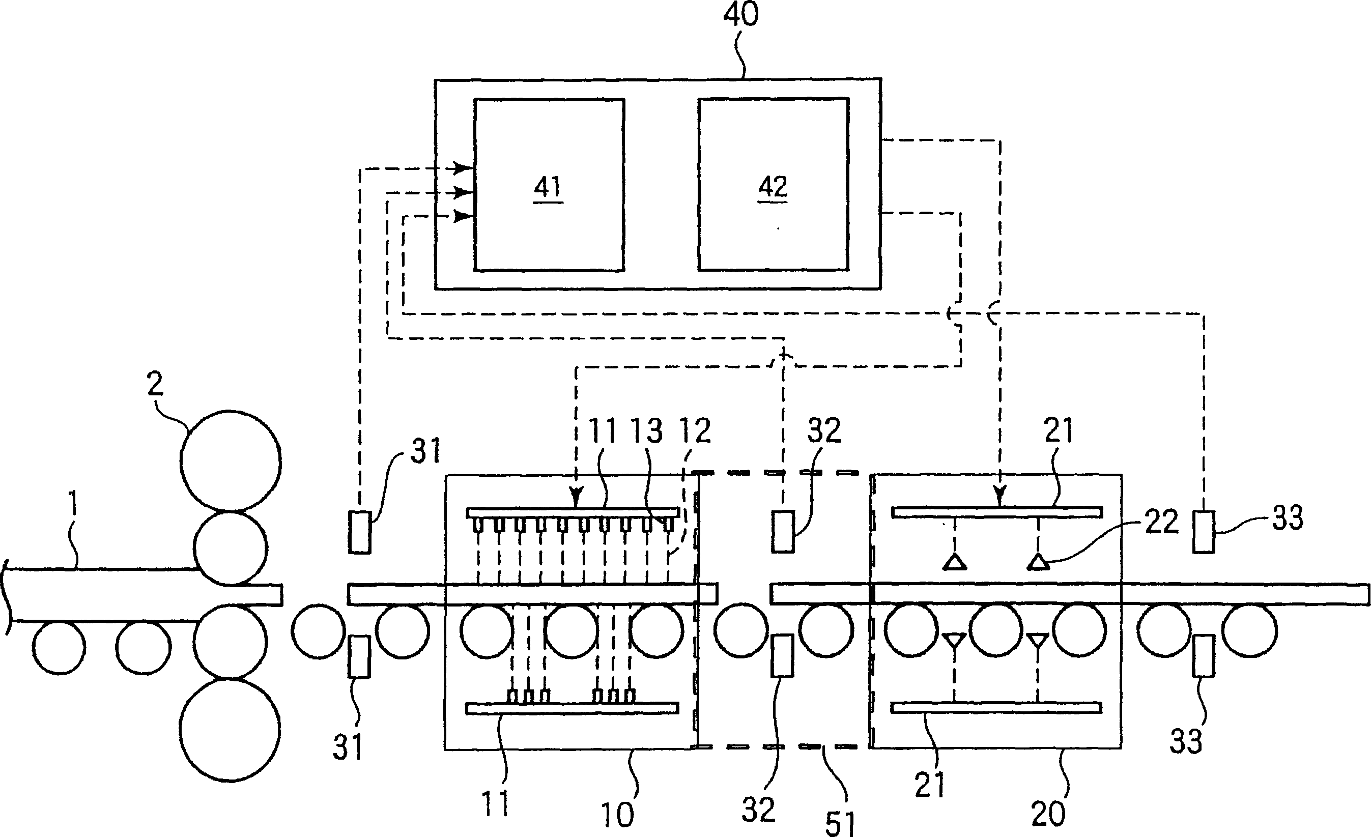
[0070] use has figure 2 The control cooling device for the thick steel plate with the basic structure shown in the figure controls the amount of ferrite formed in the slow cooling zone, and then rapidly cools it in the rapid cooling zone to produce a thick steel plate with a small difference in hardness between the surface and the center . The basic specifications of the equipment, the characteristics of the processed materials, and the processing mode are shown in Table 1.
[0071] Table 2 shows the results of comparing the operation results of the controlled cooling according to the present invention (invention examples 1 to 3) with those of the comparative examples. Among them, Comparative Example 1 is the case of using only a cooling device with a quenching zone, and Comparative Example 2, as shown in Patent Document 1, is in Ar 3 Above temperature, Ar 3 End rolling at a temperature below +50°C, and set the cooling start temperature to Ar 3 Below temperature, Ar 3 An...
Embodiment 2
[0075] A low-yield-ratio steel plate was manufactured using the same controlled cooling device as that used in Example 1. The characteristics and processing modes of the processed materials are shown in Table 3.
[0076] Table 4 shows the operation results of controlled cooling according to the present invention (invention examples 4 to 5) and comparative examples. Among them, Comparative Example 4 is to make the thick steel plate stand by, and let it cool to Ar 3 After the phase transition point is 740°C, it is cooled to about 450°C in the quench zone. Comparative example 5 is the case of cooling to about 450 degreeC only in an annealing zone based on patent document 3. Comparative Example 6 is based on Patent Document 4, after being cooled by slow cooling zone, it is reheated to Ar 3 Below -20℃, Ar 3 After the range of -100°C or higher (640°C to 720°C in this example), it is cooled to about 450°C in the quenching zone. In Comparative Example 7, the steel was cooled to a...
Embodiment 3
[0078] Using the same device as the controlled cooling device used in Example 1, the temperature at the exit side of the slow cooling zone was measured, and based on this value, the cooling conditions of the rapid cooling zone were changed to perform controlled cooling of the thick steel plate. The characteristics and processing conditions of the processed materials are shown in Table 5.
[0079] Table 6 shows the comparison between the actual results of the operating parameters and the existing operating parameter targets when the temperature at the exit side of the slow cooling zone is measured in the above operation, and the cooling conditions of the rapid cooling zone are changed based on this value to perform controlled cooling of thick steel plates the result of. In Inventive Example 6, the actual cooling stop temperature in the annealing zone was about 40°C higher than the target. Therefore, when cooling is carried out at the plate passing speed of the quenching zone o...
PUM
| Property | Measurement | Unit |
|---|---|---|
| thickness | aaaaa | aaaaa |
| length | aaaaa | aaaaa |
| tensile strength | aaaaa | aaaaa |
Abstract
Description
Claims
Application Information