Double roller continuous casting magnesium alloy thin strip casting device

A magnesium alloy and thin strip technology, which is applied in the field of metal casting, can solve the problems of inconsistency in the surface shape of the liquid film on the upper and lower surfaces of the condensation zone, the inconsistency of the cooling effect of the upper and lower rolls, and the oxidation of the magnesium alloy liquid, so as to avoid fluctuations in the liquid level of the molten pool and clamping The formation of slag, the weakening of harmful disturbances, and the effect of ensuring stability

Inactive Publication Date: 2006-07-19
CHONGQING UNIV
View PDF0 Cites 12 Cited by
  • Summary
  • Abstract
  • Description
  • Claims
  • Application Information

AI Technical Summary

Problems solved by technology

The production of aluminum alloy sheets by the horizontal double-roll method is mature and has been widely used at home and abroad. Although this process is easy to control and the process flow is simple, it has the following disadvantages: 1. The short contact area makes the formation of the solidified shell more difficult. Long cooling time; 2. The cooling effect of the upper and lower rolls is inconsistent, and the surface morphology of the liquid film on the upper and lower surfaces of the condensation zone is inconsistent, resulting in uneven quality of the upper and lower surfaces of the casting belt and internal structure
Yet adopt this device to pour magnesium alloy and can produce following process problem: 1. the oxidation problem of magnesium alloy liquid
However, the structure of conventional twin-roll continuous casting is adopted, so that the protective film on the surface of the molten pool is directly in contact with the rotating crystallization roll
see Figure 4 (a), as the casting rolls rotate, the protective film on the surface of the molten pool is easily brought into the solidification zone to form slag inclusions, which affects the quality of the cast strip; The performance requirements are extremely high, and the slight fluctuation of the liquid level in the molten pool will affect the initial solidification of the metal cast strip during continuous casting, and affect the quality of the cast strip

Method used


Image

  • Double roller continuous casting magnesium alloy thin strip casting device
  • Double roller continuous casting magnesium alloy thin strip casting device
  • Double roller continuous casting magnesium alloy thin strip casting device

Examples


Embodiment Construction

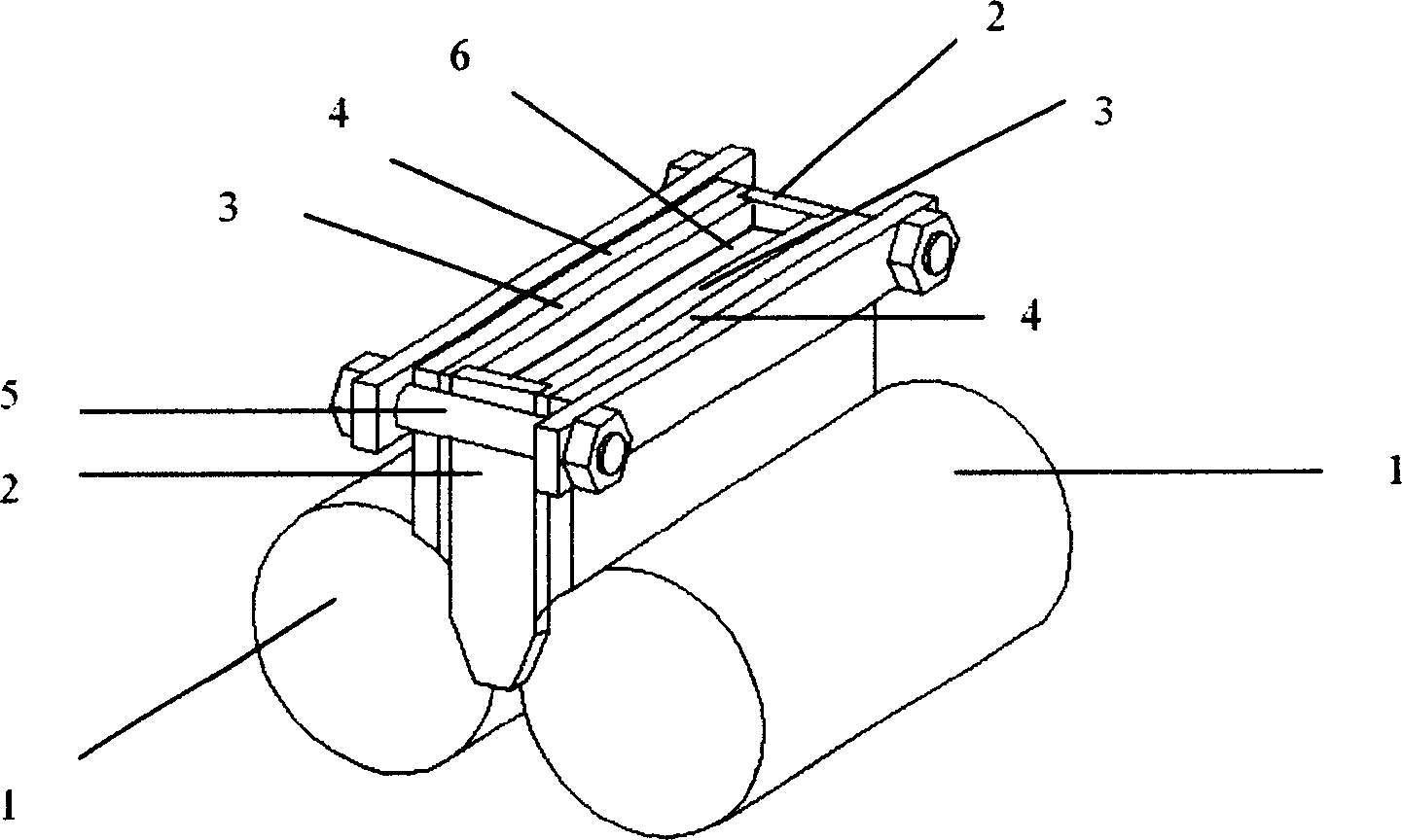
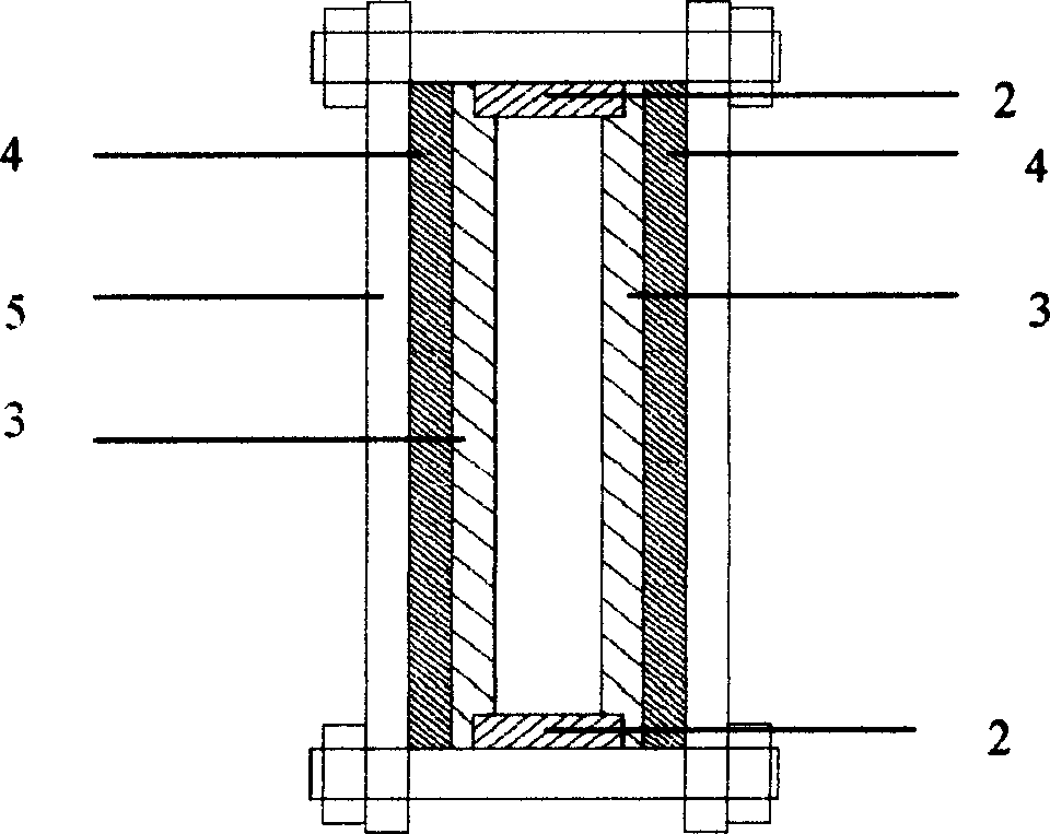
[0026] see figure 2 and image 3 . Adopt the usual side sealing plate structure. The side sealing plate 2 is supported beside the end face of the casting roll through the support structure, the working surface of the side sealing plate is opposite to and parallel to the end face of the casting roll, and the working surface of the side sealing plate is in close contact with the end face of the casting roll; the working surface of the side sealing plate Set textured. The baffle plate 3 is placed on the surface of the casting roll along the axial direction of the casting roll 1, and the baffle plate is in direct contact with the casting roll, and its contact surface is an arc surface. The baffle plate 3 is bonded with the side sealing plate 2 to form a closed rectangular groove as a molten pool. The molten pool is reinforced with a fastening device 5, and its fastening degree can be adjusted by a screw, and the height of the top of the baffle plate is consistent with that of...


PUM


Abstract

The invention discloses a two-roll continuous-casting magnesium alloy band casting device, which is characterized by the following: two end faces of forging roll connects the side closing board through support structure; the baffle is placed on the rectangle groove with all-around sealing of forging roll surface and side closing board; the rectangle groove is reinforced by fastening device; the bottom of baffle connects the forging roll directly, whose touch face displays arc face; the working face of baffle faces roll gap of two forging rolls; the function board is connected on the back of baffle working face, which connects the forging roll stickly. The invention can improve the liquid height greatly, which is easy to realize submersible casting to improve the casting band mould quality.

Description

technical field [0001] The invention belongs to the field of metal casting, and particularly relates to a twin-roller continuous casting magnesium alloy strip casting device with stable liquid level in a molten pool, no contact with rotating casting rolls on the surface protection film of the molten pool, and good casting strip quality. Background technique [0002] Magnesium alloy has low density, high specific strength, and good thermal and electrical conductivity; at the same time, it has good damping and shock absorption and electromagnetic shielding properties, and can be used in electronic devices, such as mobile communications, laptop computers, etc., and can replace plastics to meet product requirements. Light, thin, miniaturized, high integration and other requirements, the market prospect is good. However, due to the crystal structure characteristics of the hexagonal crystal system of the magnesium alloy, the processing procedure is long and the yield is low. The y...

Claims


Application Information

Patent Timeline
Patent Type & Authority Applications(China)
IPC IPC(8): B22D11/06
Inventor 丁培道杨春楣蒋斌王健戴永刚
Owner CHONGQING UNIV
Why Eureka
Try Eureka