

Fluid loss additive for boring fluid
A fluid loss reducer and drilling fluid technology, which is applied in drilling compositions, chemical instruments and methods, etc., can solve problems such as the influence of drilling fluid viscosity, high production cost, and thickening effect.
- Summary
- Abstract
- Description
- Claims
- Application Information
AI Technical Summary
Problems solved by technology
Method used
Image

Examples
Embodiment 1
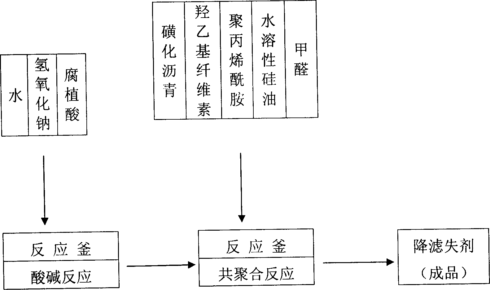
[0021] a. Weak acid and alkali reaction: take 5 tons of reactor as base weight ratio (weight ratio)
[0022] With the ratio of water: humic acid: sodium hydroxide: sulfonated pitch: hydroxyethyl cellulose: polyacrylamide: water-soluble silicone oil: formaldehyde, add water 10 into the reaction kettle, start stirring, slowly add sodium hydroxide 0.6 and stir After dissolving, add humic acid 2, raise the temperature to 80°C, control the temperature at 80°C, and react for 2 hours.
[0023] b. Copolymerization reaction
[0024] Add 0.7 sulfonated pitch, 0.1 hydroxyethyl cellulose, 0.04 polyacrylamide, and 0.05 water-soluble silicone oil to the reaction kettle, control the temperature at 75°C, and disperse the materials uniformly for 1 hour, then add formaldehyde 0.35, raise the temperature to 80°C, and control The temperature is 80°C, and the reaction is 3h.
[0025] c. The dry water content is less than 15%, crushed (the remainder of the standard sieve with a diameter of 2.00mm...
Embodiment 2
[0027] a. Weak acid and alkali reaction: based on 5 tons of reactor (weight ratio)
[0028] With the ratio of water: humic acid: sodium hydroxide: sulfonated pitch: hydroxyethyl cellulose: polyacrylamide: water-soluble silicone oil: formaldehyde, add water 11 into the reaction kettle, start stirring, slowly add sodium hydroxide 0.62 and stir After dissolving, add humic acid 2.5, raise the temperature to 80°C, control the temperature at 85°C, and react for 2.5h.
[0029] b. Copolymerization reaction
[0030] Add 0.75 sulfonated pitch, 0.15 hydroxyethyl cellulose, 0.05 polyacrylamide, and 0.06 water-soluble silicone oil to the reaction kettle, control the temperature at 80°C, and disperse the materials uniformly for 1 hour, then add formaldehyde 0.36, raise the temperature to 80°C, and control The temperature was 85°C and the reaction was 3.5h.
[0031] c. The dry water content is less than 15%, crushed (the remainder of the standard sieve with a diameter of 2.00mm is less tha...
Embodiment 3
[0033] a. Weak acid and alkali reaction: based on 5 tons of reactor (weight ratio)
[0034] With the ratio of water: humic acid: sodium hydroxide: sulfonated pitch: hydroxyethyl cellulose: polyacrylamide: water-soluble silicone oil: formaldehyde, add water 12 to the reaction kettle, start stirring, slowly add sodium hydroxide 0.62 and stir Until dissolved, then add humic acid 3, raise the temperature to 80°C, control the temperature at 90°C, and react for 3h.
[0035] b. Copolymerization reaction
[0036] Add 0.8 sulfonated pitch, 0.2 hydroxyethyl cellulose, 0.06 polyacrylamide, and 0.07 water-soluble silicone oil to the reaction kettle, control the temperature at 85°C, and disperse the materials uniformly for 1 hour, then add formaldehyde 0.39, raise the temperature to 80°C, and control The temperature was 90°C and the reaction was 4h.
[0037] c. The dry water content is less than 15%, crushed (the remainder of the standard sieve with a diameter of 2.00mm is less than 5%),...
PUM
 Abstract
Description
Claims
Application Information