Piezoelectric valve based on piezoelectric stack driver

A driver and piezoelectric stack technology, applied in the direction of valve lift, valve details, valve device, etc., can solve the problems of reduced response frequency, increased capacitive load of piezoelectric stack, increased capacitive capacitance, etc., to avoid clearance errors And the effect of response delay, simplified structure, and large driving force

A driver and piezoelectric stack technology, applied in the direction of valve lift, valve details, valve device, etc., can solve the problems of reduced response frequency, increased capacitive load of piezoelectric stack, increased capacitive capacitance, etc., to avoid clearance errors And the effect of response delay, simplified structure, and large driving force

CN1807941AInactive Publication Date: 2006-07-26ZHEJIANG UNIV

Image

  • Piezoelectric valve based on piezoelectric stack driver
  • Piezoelectric valve based on piezoelectric stack driver

Examples


Embodiment Construction

[0015] The present invention will be further described below in conjunction with the accompanying drawings and embodiments.

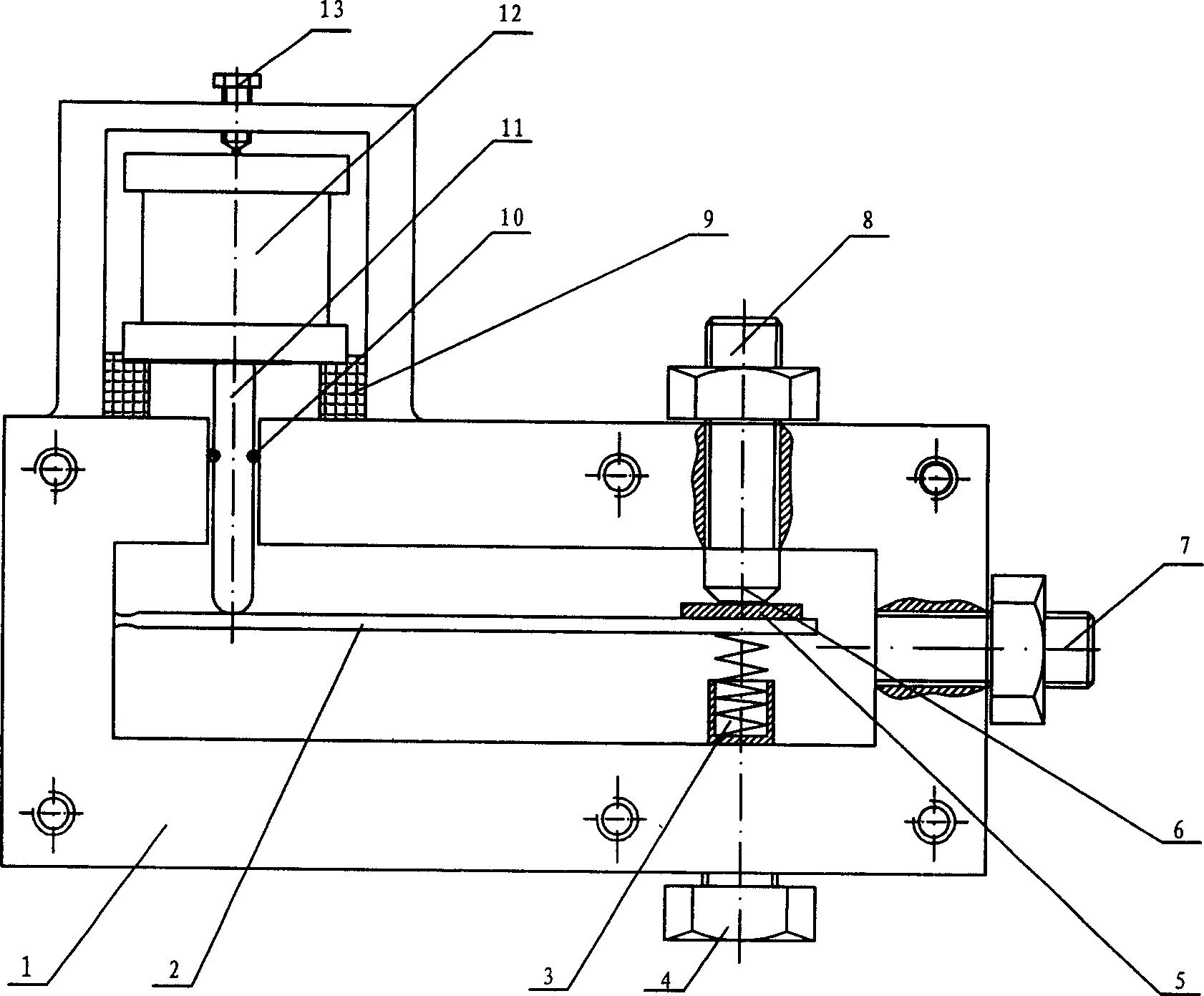
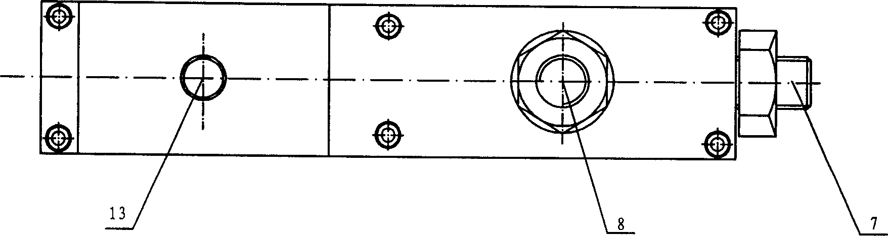
[0016] Such as figure 1 , figure 2 As shown, the present invention includes a valve body 1, an elastic baffle 2, a force regulating spring 3, a force regulating screw 4, a sealing disc 5, an air outlet nozzle 6, an air inlet 7, an air outlet 8, an elastic support 9, and a sealing gasket 10 , driving rod 11, piezoelectric stack driver 12 and adjusting screw 13; in the sealed valve body 1, a hinge is connected to one side of the elastic baffle 2, and the lower end of the elastic baffle 2 other side is equipped with a force regulating spring 3, The force regulating spring 3 is connected with the force regulating screw 4, the upper end of the other side of the elastic baffle 2 is equipped with a sealing disc 5, the sealing disc 5 is connected with the gas outlet 8 of the gas outlet nozzle 6, and the valve body 1 is equipped with an air inlet end, the ela...


PUM


Abstract

The invention relates to a piezoelectric gas valve used in piezoelectric pile driver. Wherein, the valve is connected to one side of flexible baffle plate via hinge, and the lower end of another side has a force adjustable bolt while the upper end has a sealing disc and connecting the gas outlet; the valve has a gas inlet; the flexible support outside the valve contacts one end of piezoelectric pile driver while another end contacts the adjustable bolt; the upper end of one side of flexible baffle plate contacts one end of drive rod that inserting the valve and be sealed via the sealing cushion; the another end of drive rod that extending outside the valve contacts one end of piezoelectric pile driver. The invention uses piezoelectric pile driver with displacement amplifying function, and the baffle plate with flexible hinge as the baffle plate of nozzle baffle piezoelectric gas valve, with the advantages of straight motion and bended piezoelectric gas valve to confirm enough drive force and output displacement and avoid the gap error and response delay caused by the common lever amplifying device. The invention can be used in middle high pressure area with large flux, quick response and high drive force.

Description

technical field [0001] The invention relates to a piezoelectric valve based on a piezoelectric stack driver. Background technique [0002] Piezoelectric ceramic driver is a new type of micro-displacement driving device developed in recent years. It has the advantages of compact structure, small size, high resolution, fast response, and easy control. However, whether it is a direct-acting type, a bending type, or a torsional piezoelectric valve, there are defects that are difficult to overcome. The direct-acting piezoelectric valve has two problems. One is the problem of its small flow rate: due to the limitation of the expansion and contraction length of the piezoelectric stack (generally not exceeding 30um, otherwise the number of superimposed layers of the piezoelectric stack will be large, which directly leads to piezoelectric The increase of the capacitive load, and then the response frequency is greatly reduced), and the compensation of the elastic deformation of each ...

Claims


Application Information

Patent Timeline
26 Jul 2006
Publication
CN1807941A
IPC
F16K1/20; F16K31/02
Inventors
魏燕定; 赖小波