Heat radiating structure and temperature control method

A technology of heating wire and heating temperature, applied in the direction of electric heating device, heating element, heating element shape, etc., can solve problems such as increasing cost, increasing failure rate, and causing fire

Active Publication Date: 2006-07-26
FAN YU HEALTH TECH BUSINESS CO LTD
View PDF6 Cites 9 Cited by
  • Summary
  • Abstract
  • Description
  • Claims
  • Application Information

AI Technical Summary

Problems solved by technology

[0007] 1. Most of the known technologies need to set two circuits of heating and detection in the heating pad or heating structure at the same time, and four contact parts (connecting to the two circuits respectively) are extended outwards, and the heating and comparison circuits need to be connected respectively , the configuration of electronic components is complicated, which will increase the cost of manufacturing and increase the failure rate
[0008] 2. Regardless of whether a single PTC alloy is used to achieve the two functions of heating and detection at the same time, or to achieve the above functions through two different circuits, when the temperature control device of the heating structure is damaged, the heating wire will continue to heat up, and there is There is a risk of fire; for this phenomenon, the above-mentioned known technologies cannot provide safety guarantees by virtue of the characteristics of PTC components

Method used


Image

  • Heat radiating structure and temperature control method
  • Heat radiating structure and temperature control method
  • Heat radiating structure and temperature control method

Examples


Embodiment Construction

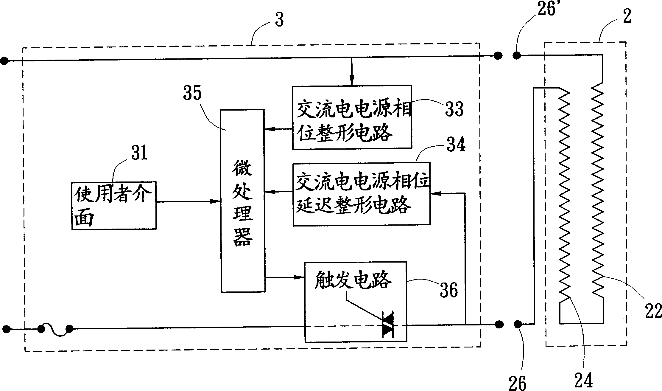
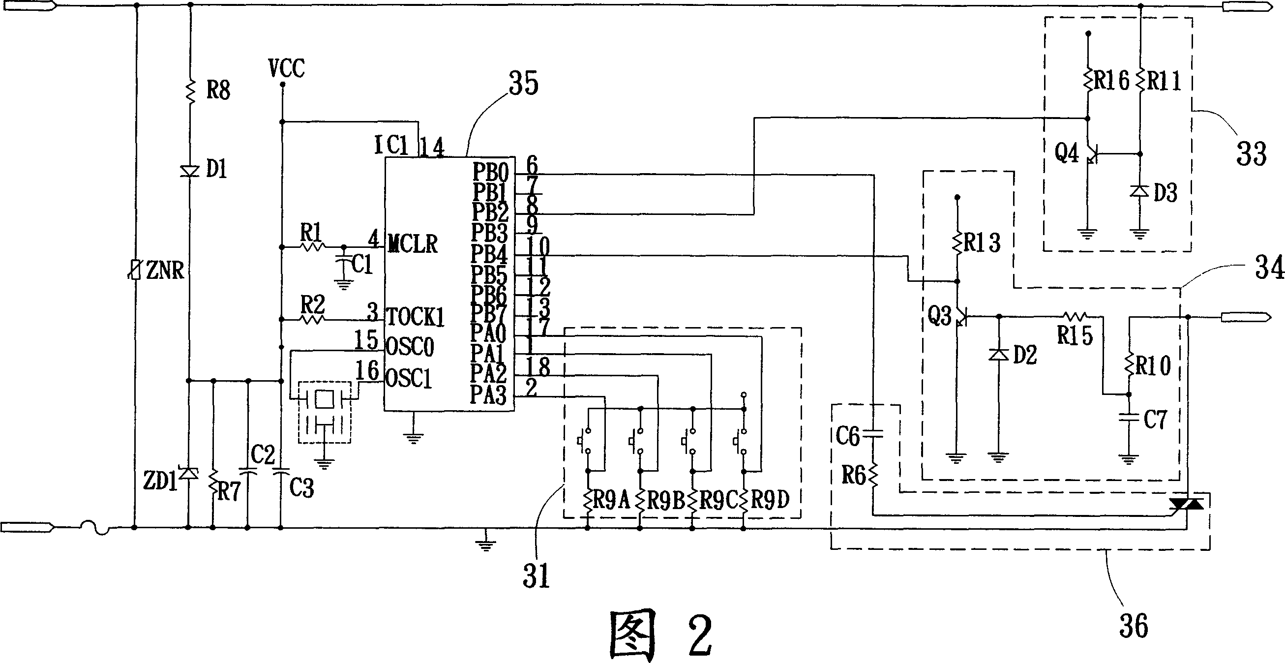
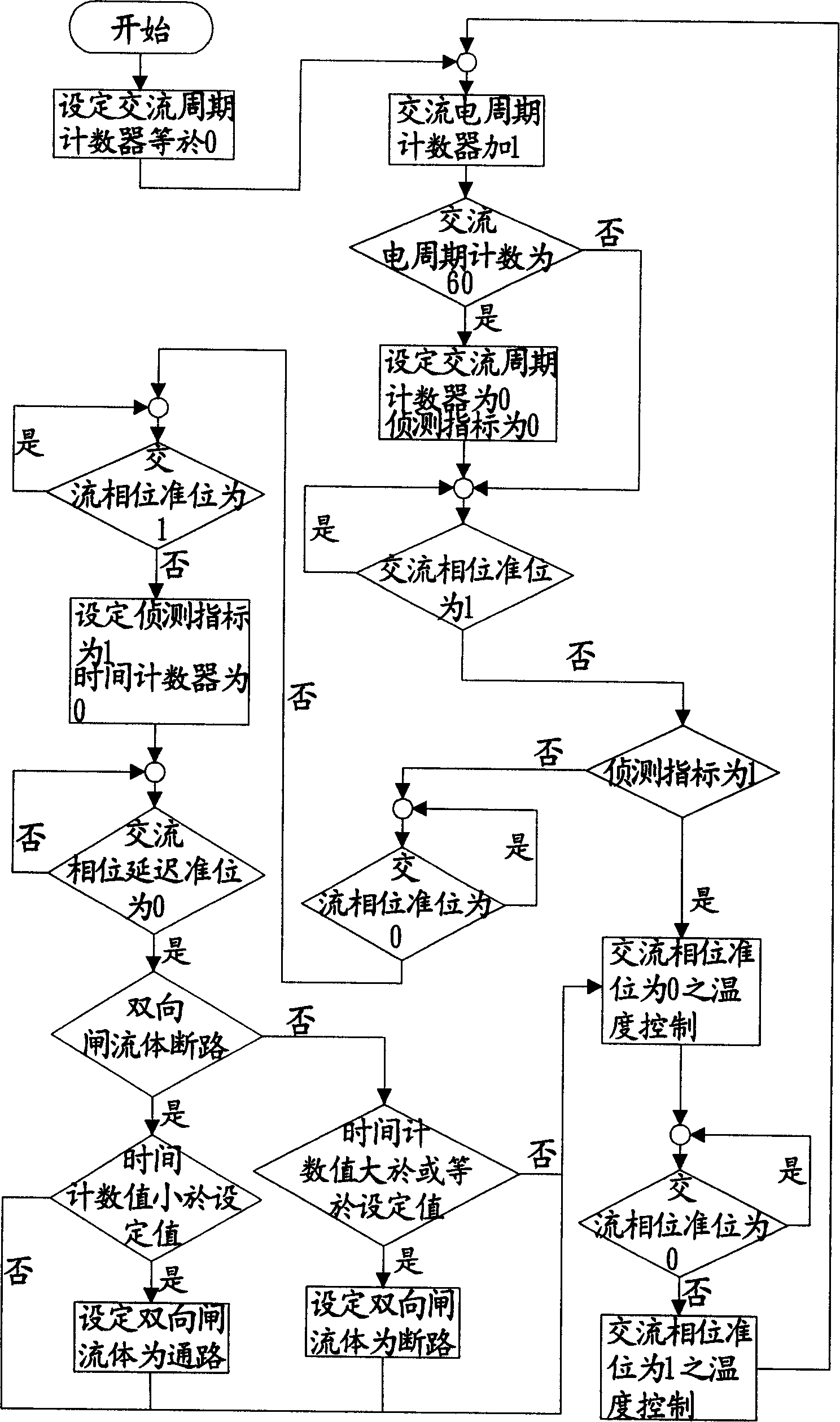
[0026] see figure 1 , the temperature control method of the heating structure of the present invention shown in Fig. 2, comprises the following steps:

[0027] a. The user sets the heating time and temperature through the user interface 31 and turns on the power.

[0028] b. Heating the positive temperature coefficient component 22, and inputting part of the current into the AC power phase shaping circuit 33 to shape it into a DC square wave.

[0029] c. A part of the conduction current is shunted into the phase delay shaping circuit 34 of the AC power supply, so that the sine wave signal is delayed, and then converted into a DC square wave signal.

[0030] d. During the heating process of the PTC component 22, the microprocessor 35 performs timing detection and compares the phase shift between the DC square wave signals converted by the AC power phase shaping circuit 33 and the AC power phase delay shaping circuit 34 respectively.

[0031] e. Control the switch (TRIAC) of ...


PUM


Abstract

This invention discloses a heating structure and its temperature controlling method, which mainly includes a heating line and a controller that are connected, wherein the heating line is arranged with the PTC component and short path which are obstructed with an insulated fusible layer; when the users arranges the heating temperature, then the current conducts the PTC component to add temperature, and it changes the sine wave signal of the input AC power phase shaping circuit and the DC power phase prolonging shaping circuit into DC square wave signal, and the microprocessor checks the phase moving change of the twice shaping circuit to control the on-off of the trigger circuit, which can make PTC component add or lower its temperature continuously to keep the heating line on a certain working temperature. This invention is applied in the heating device such as the heating stove, foment carpet and so on.

Description

technical field [0001] The invention relates to a heating structure and a temperature control method thereof, in particular to a heating structure using a PTC component, and using the characteristics of the PTC component to make the DC square wave respectively converted by the phase shaping circuit of the AC power supply and the phase delay shaping circuit of the AC power supply. The signal generates a phase shift to control the switch of the trigger circuit in real time to heat or cool down the PTC component, so that the heating wire can be kept at a certain working temperature; it is suitable for heating devices such as electric furnaces and heating blankets. Background technique [0002] Heating structures have been widely used at present, such as Figure 7 As shown, it is a fairly common heat pad structure. A group of upper and lower conductive plates a1 are mainly installed in a set of bags, and a plurality of ceramic resistors a2 are sandwiched between the two conductiv...

Claims


Application Information

Patent Timeline
Patent Type & Authority Applications(China)
IPC IPC(8): H05B1/02H05B3/54H05B3/06
Inventor 杨顺在
Owner FAN YU HEALTH TECH BUSINESS CO LTD
Why Eureka
Try Eureka