
Four-cycle engine

A four-stroke engine, engine technology, applied in the direction of engine components, machines/engines, mechanical equipment, etc., can solve problems such as cost increase, and achieve the effects of suppressing deviation, promoting activation, and improving exhaust gas purification performance

Inactive Publication Date: 2006-07-26
YAMAHA MOTOR CO LTD
View PDF2 Cites 3 Cited by
  • Summary
  • Abstract
  • Description
  • Claims
  • Application Information

AI Technical Summary

Problems solved by technology

In order to realize the fuel injection system, fuel pumps, fuel regulators, controllers, etc. must be added, which increases the cost

Method used


Image

  • Four-cycle engine
  • Four-cycle engine
  • Four-cycle engine

Examples


Embodiment Construction

[0024] The embodiments of the present invention will be described below in conjunction with the drawings.

[0025] figure 1 It is a schematic diagram for explaining a four-stroke engine according to an embodiment of the present invention according to claims 1, 3, and 4.

[0026] In the figure, reference numeral 1 denotes a four-stroke engine used in a motorcycle such as a motorcycle or a scooter. The intake passage 2 is connected to an intake port (not shown) of the engine 1, a carburetor used as a fuel supply system is provided in the middle of the intake passage 2, and an air cleaner 4 is connected to the upstream end of the intake passage 2 . The structure of the air cleaner 4 is such that the inside of the filter case 4a is partitioned into the air suction side "a" and the discharge side "b" by the member 5.

[0027] The carburetor 3 includes an idling system working in the idle and low-speed driving zones and a main system working in the medium-speed and high-speed driving ...


PUM


Abstract

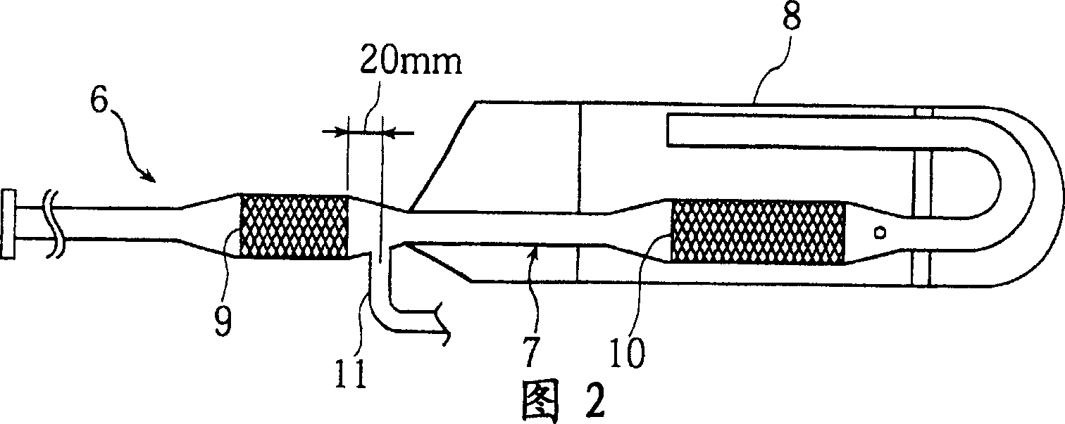
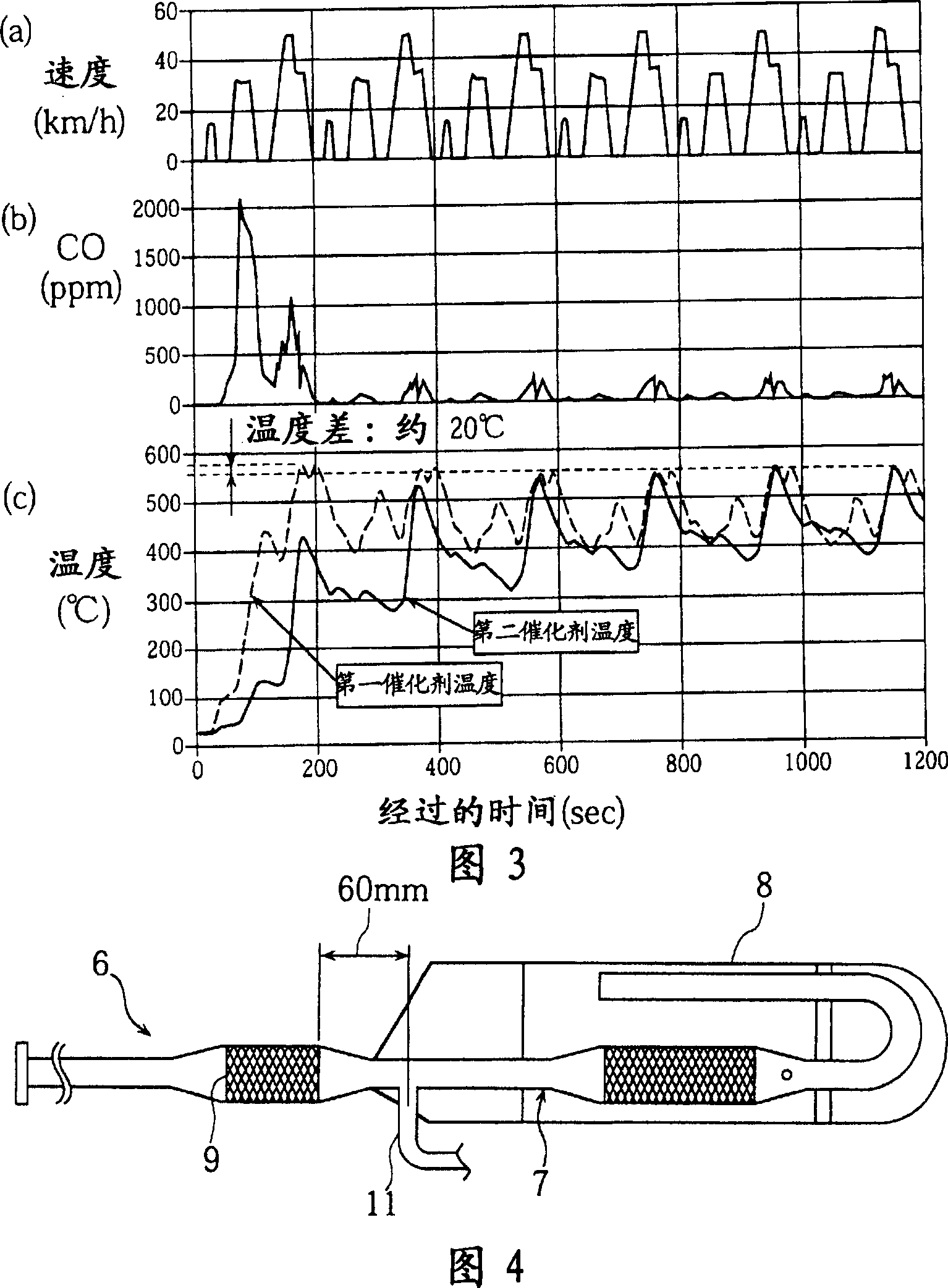
The present invention provides a four-stroke engine. A first catalyst (9) is provided in an exhaust pipe (6), and a second catalyst (10) is provided in the exhaust pipe (6), on the downstream side of the first catalyst (9), with a spacing from the first catalyst (9). A secondary air-introducing pipe (11) for introducing secondary air is connected to a portion between the first and the second catalyst (9, 10), at a position where the difference between the maximum temperatures of the first and the second catalyst (9, 10) in a measurement operation range is within a predetermined temperature range.

Description

Technical field [0001] The invention relates to a four-stroke engine, wherein an exhaust pipe is connected to the exhaust port of the engine, and a catalyst is arranged in the exhaust pipe and secondary air is introduced. Background technique [0002] Generally speaking, in the relationship between the air-fuel ratio (A / F) of a four-stroke engine and the exhaust gas composition, such as Figure 15 As shown, the exhaust gas composition changes significantly with an air-fuel ratio of 14.6 (theoretical air-fuel ratio = stoichiometric ratio). In other words, the emissions of CO and HC are larger on the rich side where the air-fuel ratio is greater than the stoichiometric ratio, and smaller on the lean side. On the other hand, on the contrary, near the stoichiometric ratio, the NOx emissions are small on the rich side and large on the lean side. [0003] Picture 11 with 12 Shows such a conventional engine equipped with an exhaust gas purifier for achieving the removal of CO, HC, and...

Claims


Application Information

Patent Timeline
Patent Type & Authority Applications(China)
IPC IPC(8): F01N3/30F01N3/22F01N3/24
Inventor 西村英浩大场纯一泷井修
Owner YAMAHA MOTOR CO LTD
Learn More