
Control method for measuring colour difference

A control method and color measurement technology, applied in the direction of color measurement using electric radiation detectors, color measurement devices, etc., can solve the problems of large errors, the inability to quantitatively determine the specific number of color differences, and the inability to judge test products, etc., to achieve The effect of small error, easy operation and simple steps

Inactive Publication Date: 2006-08-02
北京机械工业学院
View PDF0 Cites 6 Cited by
  • Summary
  • Abstract
  • Description
  • Claims
  • Application Information

AI Technical Summary

Problems solved by technology

[0002] Among the existing methods for measuring color difference, most of them use artificial methods to judge their differences by directly comparing colors with eyes. Although this method is simple, it cannot quantitatively determine the specific amount of color difference, and the error in the whole operation process is relatively large. , similar test items cannot be judged

Method used


Image

  • Control method for measuring colour difference
  • Control method for measuring colour difference

Examples


Embodiment 1

[0024] Embodiment one: measure the chromatic aberration of dilute red ink

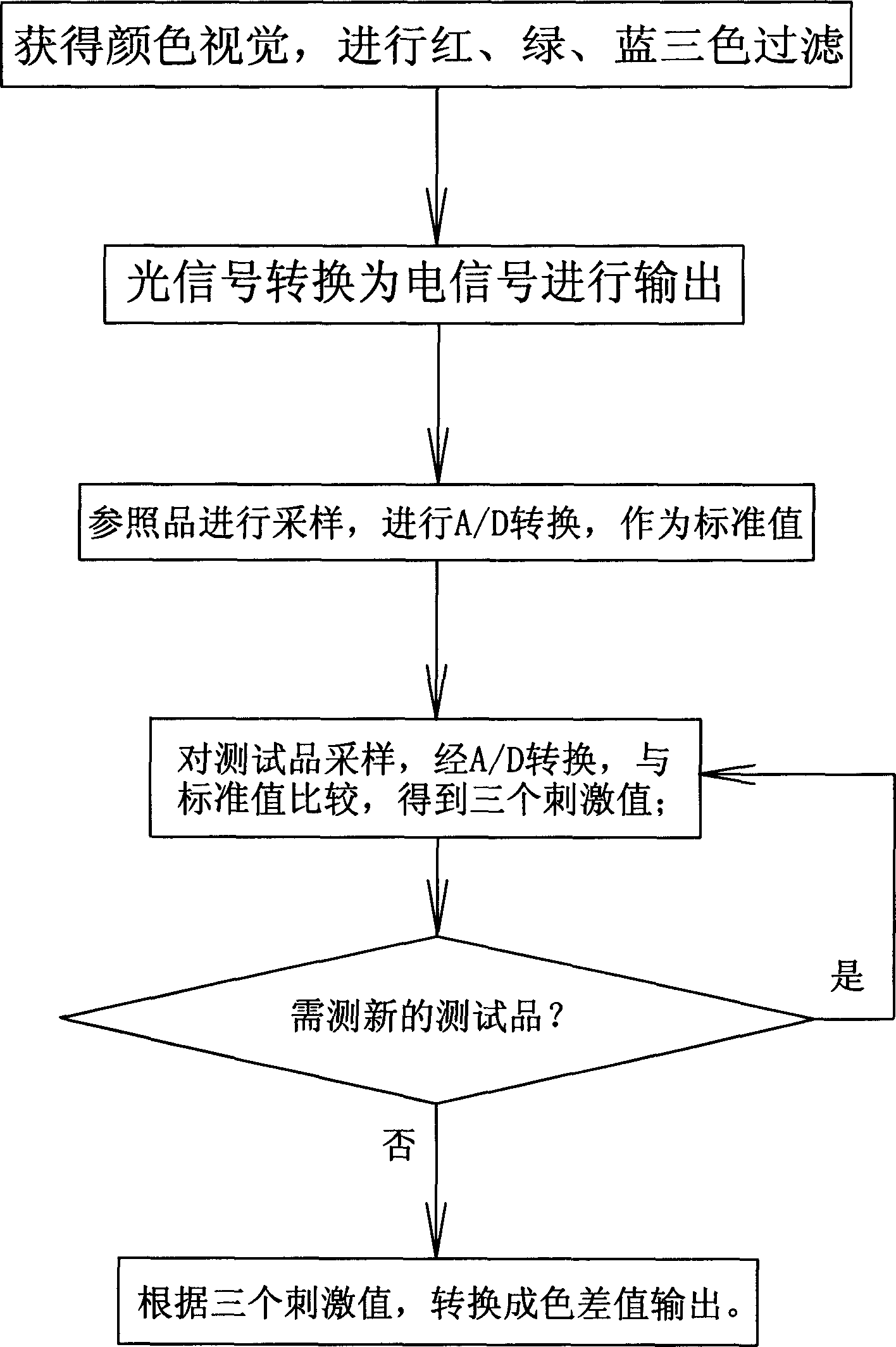
[0025] Add two drops of red ink in the water, and under the background of the standard lighting body D65, first test the color vision of the water with the sampling sensor (probe), pass the red, green and blue filters for the color vision, and then put the The optical signal obtained by filtering is converted into an electrical signal by a photodetector, and then the electrical signal is converted by A / D, and the value is set to zero; then the probe is used to test the thin red ink, and the color vision is filtered by three colors The optical signal obtained after the film is converted into an electrical signal by a photodetector, and then the value obtained by A / D conversion is the tristimulus value (X, Y, Z) of the dilute red ink.

[0026] Convert tristimulus values ​​(X, Y, Z) into lightness (L * ) and chroma (a * , b * ), calculated by the following formula:

[0027] L * =116(Y / Y n ) 1 / 3 -16...

Embodiment 2

[0033] Example 2: Two different patterns on the same white paper

[0034] Under the background of the standard illuminant D65, first test the color vision of the white paper with the sampling sensor (probe), pass the red, green and blue color filters for the color vision, and then pass the light signal obtained by the filter through the photoelectric The detector is converted into an electrical signal, and then the electrical signal is converted through A / D, and the value is set to zero; then the probe is used to test one of the patterns, and the optical signal obtained by the color vision through the three-color filter, It is converted into an electrical signal by a photodetector, and then the value obtained through A / D conversion is the tristimulus value (X 1 , Y 1 ,Z 1 ); and then test another pattern with the probe, the optical signal obtained by the color vision through the three-color filter, and then converted into an electrical signal by the photodetector, and then t...


PUM


Abstract

The present invention discloses a control method for measuring colour difference. Said control method includes the following steps: firstly, utilizing sampling sensor to obtain colour visual sensation, making the colour undergo the process of red, green and blue three-colour filtration, and converting the filtered three-colour light signal into electric signal to make output; sampling reference sample to obtain the correspondent electric signal, making said electric signal undergo the process of A / D conversion and using it as standard value; sampling test sample to obtain electric signal, comparing the value obtained after the above-mentioned electric signal is undergone the process of A / D conversion with the above-mentioned standard value so as to obtain correspondent three stimulation values; again sampling new reference sample to define new standard value, judging new test sample to obtain new stimulation values; converting collected three stimulation values into colour difference value and making output.

Description

technical field [0001] The invention relates to a control method for measuring color difference. Background technique [0002] Among the existing methods for measuring color difference, most of them use artificial methods to judge their differences by directly comparing colors with eyes. Although this method is simple, it cannot quantitatively determine the specific amount of color difference, and the error in the whole operation process is relatively large. , similar test items cannot be judged. Contents of the invention [0003] The technical problem to be solved by the present invention is to avoid the deficiencies in the above-mentioned prior art, and propose a control method for color difference measurement with accurate detection and simple process. [0004] The technical solution provided by the present invention is: the control method includes the following steps [0005] First, the color vision is obtained through the sampling sensor, and the color is filtered b...

Claims


Application Information

Patent Timeline
IPC IPC(8): G01J3/51G01J3/46
Inventor 徐小力
Owner 北京机械工业学院
Learn More