Driver and driving method for semiconductor light-emitting element array

A technology of light-emitting components and driving methods, which is applied to electrical components, electroluminescent light sources, instruments, etc., and can solve problems such as the inability to dynamically contrast and adjust the scanning backlight mode or color sequence of liquid crystal display screens

Active Publication Date: 2006-08-02
AU OPTRONICS CORP
View PDF2 Cites 18 Cited by
  • Summary
  • Abstract
  • Description
  • Claims
  • Application Information

AI Technical Summary

Problems solved by technology

This patent points out that the current of the LED array module can be regulated by the current mirror (Current Mirror) composed of MOSFETs and the compensation of the controller to achieve the purpose of regulating the current of the LED array, but this kind of control method only achieves the current balance of the LED array The effect of balancing the color temperature with the mixed light, and cannot further cooperate with the LCD screen to achieve functions such as dynamic contrast adjustment, scanning backlight mode, or color sequence
[0004] In addition, U.S. Patent No. 6,864,867B2 proposes another driving circuit for an LED array module. Its structure is composed of a set of controllers, a set of transistors, and an LED array. However, the control method of this patent is also as described in the aforementioned patent The method uses the controller to drive the transistor to achieve the effect of current sharing in the LED array module, and this kind of control method cannot make the LEDs play the most effective

Method used


Image

  • Driver and driving method for semiconductor light-emitting element array
  • Driver and driving method for semiconductor light-emitting element array
  • Driver and driving method for semiconductor light-emitting element array

Examples


Embodiment Construction

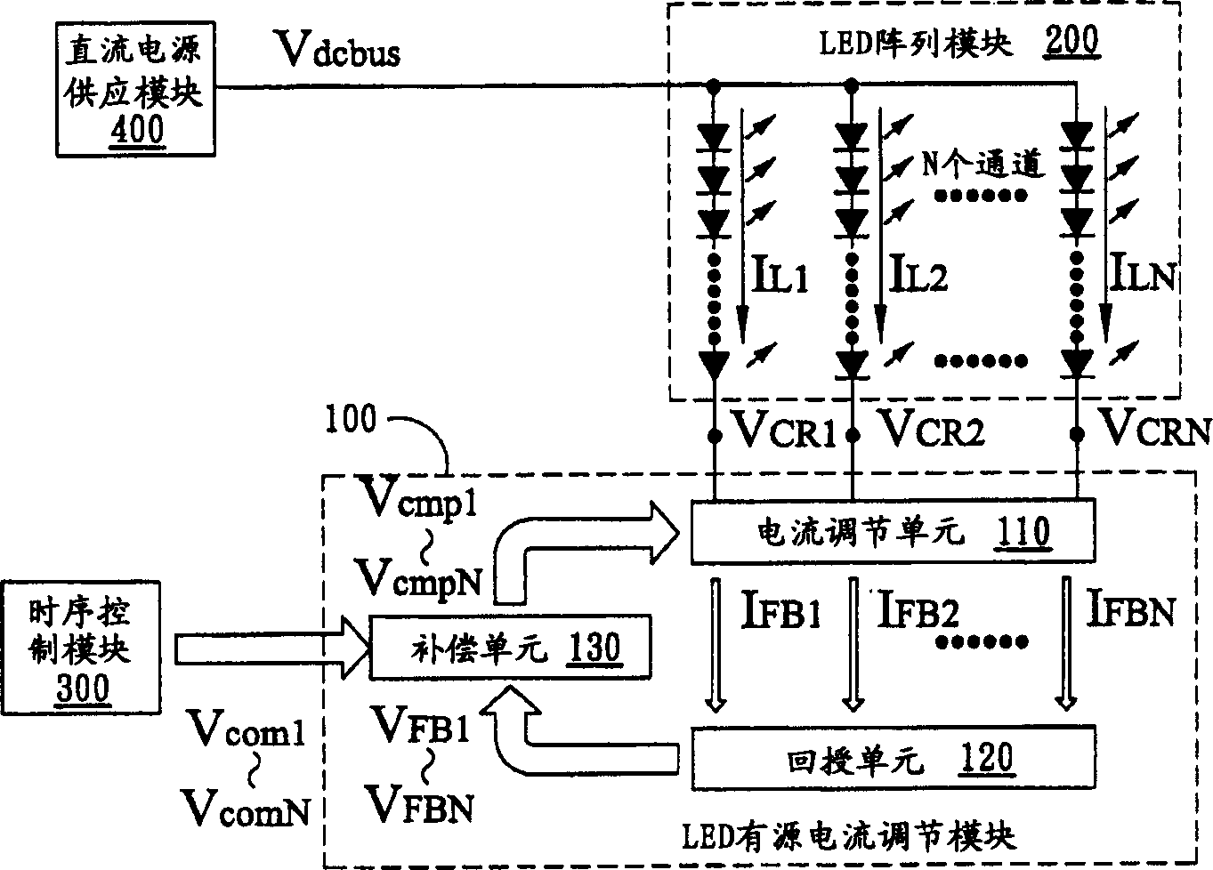
[0045] figure 1 A block diagram showing a system architecture of an active current driver for a semiconductor light emitting device according to a preferred embodiment of the present invention. In this embodiment, a light emitting diode is used as a semiconductor light emitting element, however other light emitting elements are also applicable. The LED active current driver according to this embodiment can be used to drive the LED array module 200 , and the LED active current driver at least includes the LED active current regulation module 100 , the timing control module 300 , and the DC power supply module 400 . Wherein, the LED active current regulation module 100 may at least include three parts: a current regulation unit 110 , a feedback unit 120 and a compensation unit 130 .

[0046] As shown in the figure, the DC power supply module 400 is electrically connected to the LED array module 200 , the LED array module 200 is connected to the current regulation unit 110 , and...


PUM


Abstract

This invention puts forward a driver of an array of semiconductor luminous cells including at least a current modulation unit containing multiple controllable switches for modulating volumes of each set serial current of the array, in which, the current volumes generate multiple feedback signals correspondingly via a feedback unit, a compensation unit generates related multiple control signals based on the input time sequence signals and the feedback signals to control said controllable switch, which can control the brightness and darkness and time sequence variance of the serial luminous cells.

Description

technical field [0001] The invention relates to a driving device and method of a semiconductor light emitting element array, in particular to a light emitting diode array (Light Emitting Diode Array) driver and its driving method supporting the dynamic image control function. Background technique [0002] Light-emitting diode backlights have been gradually applied to liquid crystal displays (Liquid Crystal Display; LCD), which are more environmentally friendly and have better color vividness performance than the existing Cold Cathode Fluorescent Lamp (CCFL) backlights . The LED backlight driver usually adopts constant current mode control driven by DC voltage. This type of control method is often applied to small-sized white LED backlight; or uses a current regulation integrated circuit (current sink IC) Three color controls. However, these two types of control architectures are only suitable for driving the LED module to achieve current balance and color temperature balan...

Claims


Application Information

Patent Timeline
Patent Type & Authority Applications(China)
IPC IPC(8): G09G3/34G09G3/36G09G3/20H05B33/08H05B44/00
Inventor 魏庆德叶怡君孙嘉宏李宗勋
Owner AU OPTRONICS CORP
Why Eureka
Try Eureka