Multi-frequency antenna cond design method

A multi-frequency antenna and antenna technology, applied to antennas, antenna arrays, and devices that enable antennas to work in different bands at the same time, can solve problems such as inability to install and inconvenience, and achieve reduced occupied area, increased usability, and reduced area Effect

Active Publication Date: 2006-08-09
WISTRON NEWEB
View PDF0 Cites 11 Cited by
  • Summary
  • Abstract
  • Description
  • Claims
  • Application Information

AI Technical Summary

Problems solved by technology

And although this kind of inverted F dual-band antenna can be applied to two operating frequencies for sending and receiving at the same time, the radiation element 301 in this kind of antenna structure cannot be further reduced or deformed, so it cannot be installed in a device that is too narrow in size , quite inconvenient

Method used


Image

  • Multi-frequency antenna cond design method
  • Multi-frequency antenna cond design method
  • Multi-frequency antenna cond design method

Examples


Embodiment Construction

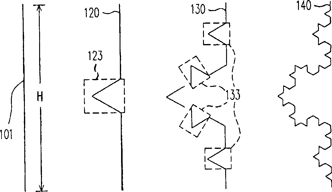
[0065] The multi-frequency antenna proposed by the present invention is characterized in that the antenna utilizes the Koch fractal antenna structure to design the antenna in a multi-circle triangle manner, which can effectively reduce the required area of ​​the antenna, and at the same time Can achieve the effect of multi-frequency work.

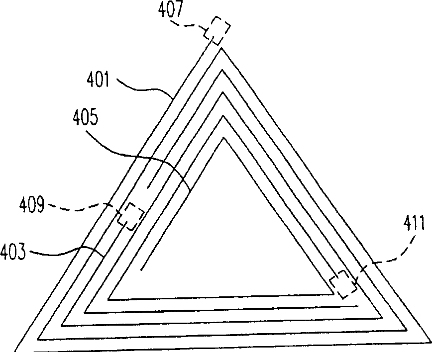
[0066] Please refer to image 3 , which shows the structural diagram of the multi-frequency antenna proposed according to the present invention. As shown in the figure, the multi-frequency antenna is composed of three groups of radiating elements 401, 403 and 405, wherein the three groups of radiating elements are all designed with the same geometric trajectory around multiple circles, in this embodiment , this geometric locus is an equilateral triangular locus. Each group of radiating elements has an input terminal 407 , 409 and 411 for receiving or transmitting signals of different frequencies.

[0067] The trajectories of equilateral ...


PUM


Abstract

Using arrangement structure of Koch fractal antenna and triangle locus circled in multiturn designs antenna in multiple frequency with smaller area than area of general structure of antenna. Using arrangement structure of Koch fractal antenna can reduce area needed by inversion F type antenna in dual frequency in order to obtain better utilization.

Description

technical field [0001] The present invention relates to a multi-frequency antenna, and in particular relates to a multi-frequency antenna designed using Koch fractal antenna technology and a design method thereof. Background technique [0002] Due to the wireless communication technology that uses electromagnetic waves to transmit signals, there is no need to connect cables to achieve the effect of remote device communication, and it also has the advantage of being easy to move, which makes the use of wireless communication technology. There are more and more types of products, such as mobile phones , notebook computers, smart home appliances that provide wireless communication functions, etc., and the above-mentioned equipment uses electromagnetic waves to transmit signals, so the antenna used to induce electromagnetic waves has also become a necessary device in the equipment applying wireless communication technology. [0003] Please refer to figure 1 , which shows a comp...

Claims


Application Information

Patent Timeline
IPC IPC(8): H01Q1/38H01Q5/00H01Q13/08H01Q21/00
Inventor 张弘岳方建兴郑维礼陈志龙
Owner WISTRON NEWEB
Why Eureka
Try Eureka