
Rotor for laboratory centrifuges

A laboratory centrifuge and laboratory technology, applied in the field of centrifuge rotors, can solve the problems of rotor shell damage, resonance, imbalance, etc., and achieve the effect of improving the stability of the bearing structure, eliminating axial displacement, and reducing imbalance

Inactive Publication Date: 2006-08-23
科峻仪器公司
View PDF2 Cites 4 Cited by
  • Summary
  • Abstract
  • Description
  • Claims
  • Application Information

AI Technical Summary

Problems solved by technology

In this way, the rotor hub protruding through the circumference of the annular groove, especially below, can cause damage and cracks to the rotor casing
It may also be due to the formation of the annular groove, for example, when the centrifuge container is subjected to uneven force, or when the centrifugal separator is loaded unevenly, it will cause the oval state of the rotor head during centrifugation
[0005] In addition, due to the high precision that must be achieved in this design, it may cause inaccuracies when the centrifugal container is adapted and debugged in the annular groove, resulting in multiple imbalances and resonance phenomena at a certain number of revolutions, etc. Danger

Method used


Image

  • Rotor for laboratory centrifuges
  • Rotor for laboratory centrifuges
  • Rotor for laboratory centrifuges

Examples


Embodiment Construction

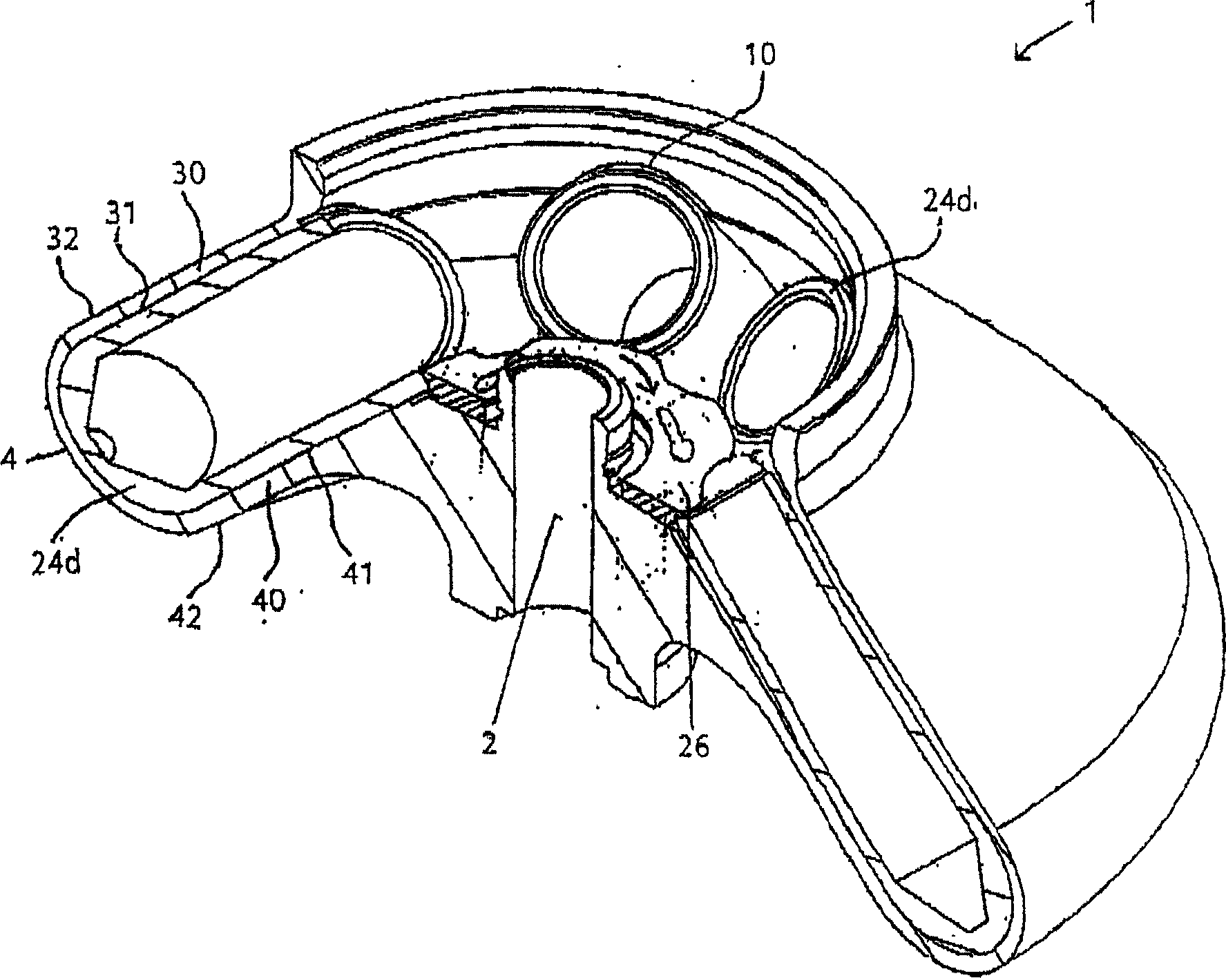
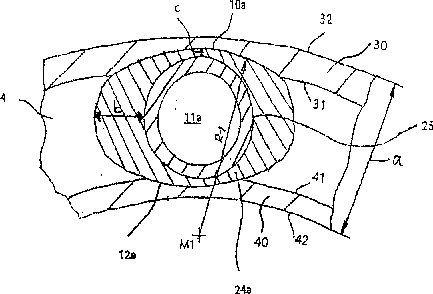
[0036] In the following drawings, the same parts will be marked with the same.

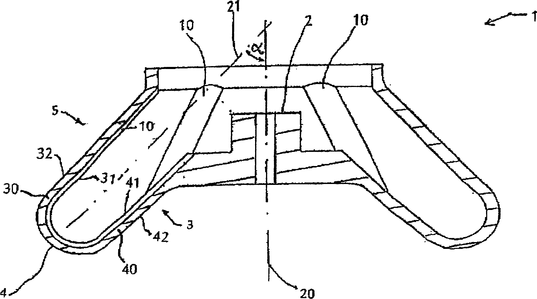
[0037] figure 1 It is a longitudinal sectional view of the entire rotor shell 1, the rotor hub 2 is assembled in the center of the truncated cone 3 that decreases from bottom to top, and the middle part of the rotor shell is composed of the truncated cone and the rotor hub 2. The truncated cone 3 is part of the annular groove 4 and a substantial part of the inner wall 40 is formed by the truncated cone 3 . In addition, in the annular groove, the concave truncated cone 5 that decreases continuously from bottom to top is located on the side opposite to the truncated cone 3 , that is, on the outer wall 30 of the rotor housing 1 formed by the concave truncated cone 5 . The annular groove 4 includes the inner edge of the inner wall 41 and the inner edge of the outer wall 31 , and the outer edge of the inner wall 42 and the outer edge of the outer wall 32 . The peripheral area consists of an annular g...


PUM


Abstract

The present invention relates to a rotor for laboratory centrifuges, said rotor comprising a rotor housing that is open to the top and at least one recess for taking up centrifuge containers, wherein the recess is formed in the peripheral area of the rotor as a concentric, circumferential ring trough having an inner wall and an outer wall and wherein the ring trough is stiffened in a spoke-type manner in such a way using centrifuge containers that are distributed radially and over the circumference of the ring trough that the centrifuge containers support the inner wall and the outer wall rigidly against one another. Furthermore, an adapter for receiving a sample container and for use in such a rotor is suggested.

Description

technical field [0001] The present invention relates to a centrifuge rotor used in a laboratory. The rotor has an upwardly flared housing. At least one sleeve that can clamp the centrifuge container should be left in the shell, so that an annular groove with both inner wall and outer wall and concentric circles is formed around the rotor; An adapter used on the laboratory centrifuge rotor. Background technique [0002] It can be seen from the list of interrelationships that, on the one hand, the centrifuge container can be a sample container for separate experiments. On the other hand, the centrifuge container can also be used as an adapter in the rotor, and the sample container can be placed inside it. [0003] The reason why rotors are used in laboratories is to clamp centrifuge containers. The separation vessel contains the substances to be separated. Centrifugal separation vessels, such as reaction tubes, fit into the cylindrical void. These can conveniently be pla...

Claims


Application Information

Patent Timeline
Patent Type & Authority Applications(China)
IPC IPC(8): B04B5/12B04B5/04B04B15/00
CPCB04B7/08B04B5/0414B04B2005/0435B04B7/085
Inventor 弗兰克·艾格梅尔苏珊娜·克罗尔莱蒙德·格罗特豪斯
Owner 科峻仪器公司
Learn More