Precise decoupling detecting method for gyroscope scale factor and input shaft default angle

A technology of scaling factor and testing method, which is applied in gyro effect for speed measurement, gyroscope/steering sensing equipment, speed/acceleration/shock measurement, etc., can solve the problem of parallelism and perpendicularity errors of sensitive axes of devices, unscientific, Calculations are inaccurate, etc.

Active Publication Date: 2006-08-23
BEIHANG UNIV
View PDF0 Cites 39 Cited by
  • Summary
  • Abstract
  • Description
  • Claims
  • Application Information

AI Technical Summary

Problems solved by technology

However, their input axis misalignment angles are relatively large. For example, MEMS gyroscopes are generally packaged in patches, which need to be soldered to the circuit board in application, and can be used with other electronic components such as resistors and capacitors. The installation of the circuit board The accuracy is far lower than the installation accuracy of traditional gyroscopes. In particular, during the manual welding process, it will cause a large error in the parallelism and perpendicularity of the sensitive axis of the device, and some even reach more than 5°. Therefore, MEMS gyroscopes The input shaft misalignment angle is very large
At present, there are relatively few reports on the testing of micro-miniature, low-cost, and low-precision gyroscopes, and there is no unified and standardized testing method. Basically, the test standards for traditional gyroscopes are used in reference. Neglecting the approximate error value will bring great errors to the improvement of the accuracy of the gyroscope, the subsequent strapdown calculation and integrated navigation. Therefore, according to the data processing model represented by formula (4) and formula (5) to test Gyroscope, it seems very unscientific, it has the following disadvantages:
[0023] 1. The scale factor K of the gyroscope calibrated by the traditional g

Method used


Image

  • Precise decoupling detecting method for gyroscope scale factor and input shaft default angle
  • Precise decoupling detecting method for gyroscope scale factor and input shaft default angle
  • Precise decoupling detecting method for gyroscope scale factor and input shaft default angle

Examples


Embodiment Construction

[0081] The specific implementation method of the present invention, in combination with Figure 4 , Figure 5 The details are as follows:

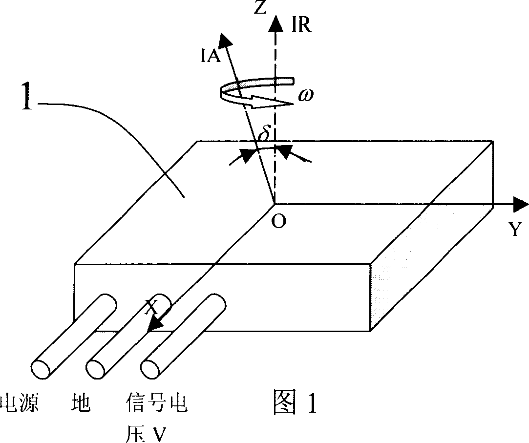
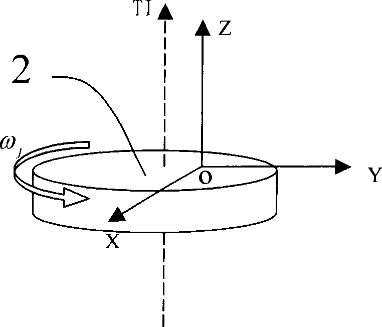
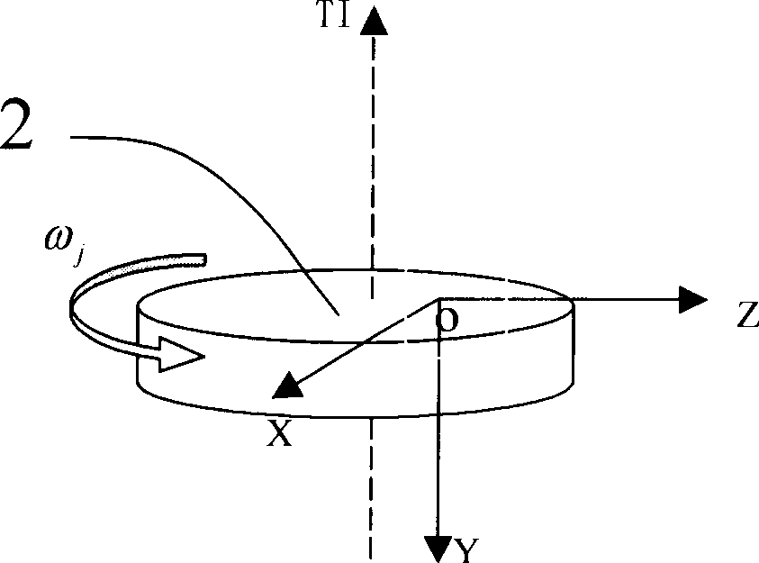
[0082] This test method includes two parts: turntable experiment and data processing. The axes of the gyroscope are specified as follows: the OZ axis coincides with the input reference axis IR, and OX and OY are perpendicular to each other in the gyroscope installation plane. Generally, OX is parallel to the output axis, and the positive directions of the three axes satisfy the requirement of OX×OY=IA Regulation;

[0083] The turntable experiment of this test method can use a three-axis turntable or a single-axis rate turntable with equipment that can provide an inclination angle. The preparation work includes the following: The ambient temperature is required to be within 15-35°C and kept relatively stable. No more than ±2°C, relative humidity between 20% and 80%, and no abnormal atmospheric pressure; the test bench is required to be i...


PUM


Abstract

This invention relates to an accurate uncoupling test method for gyro scale factor and input shaft distortion angle, which installs a gyro at state 1 to ensure the OY shaft of the gyro parallel to the swing table and regulates the OZ shaft to be in the angle of theta to the swing table shaft, then sets rate of the input angle orderly to test and record the mean value out put by the gyro when the swing table is at rest before rotating, rotates positively, idle at stopping, reversal then rest after stopping and alters the theta of step 1 to alter the states to 2,3 and 4, repeat steps of 1-3 of the gyro orderly then processes the tested data to realize the uncoupling of the scale factor and its input shaft distortion angle of a gyro.

Description

technical field [0001] The invention relates to an accurate decoupling test method for a scale factor of a gyroscope and an input axis misalignment angle, and belongs to the field of navigation, guidance and control. Background technique [0002] In the process of inertial navigation, the error caused by inertial devices usually accounts for more than 70% of the entire guidance error, which leads to higher and higher requirements for inertial devices. By improving the processing technology, the precision of the inertial device can be improved, but the cost is huge, and it brings great difficulties to mass production. Therefore, people pay more attention to the testing, calibration and compensation technology of inertial devices. Among them, inertial navigation testing technology is a new discipline developed on the basis of inertial navigation technology. It includes inertial navigation testing equipment, testing methods, and data processing technology. aspect. Through the...

Claims


Application Information

Patent Timeline
IPC IPC(8): G01C25/00G01C21/18G01C19/00
Inventor 房建成张海鹏盛蔚刘百奇全伟曹娟娟
Owner BEIHANG UNIV
Why Eureka
Try Eureka