Adaptive fuel control for an internal combustion engine

A fuel control and internal combustion engine technology, applied in engine control, fuel injection control, internal combustion piston engines, etc., can solve the problems of exhaust emission impact, high total failure rate of components, etc.

Inactive Publication Date: 2006-08-23
GENERAL ELECTRIC CO
View PDF0 Cites 14 Cited by
  • Summary
  • Abstract
  • Description
  • Claims
  • Application Information

AI Technical Summary

Problems solved by technology

However, the increased fuel flow to the remaining working cylinders creates higher than normal pressures, thereby resulting in a higher overall failure rate of the affected components
Exhaust emissions may also be affected
such failures are likely to occur if the failures are not detected by the operator and the engine is to operate in this degraded mode for an extended period of time

Method used


Image

  • Adaptive fuel control for an internal combustion engine
  • Adaptive fuel control for an internal combustion engine
  • Adaptive fuel control for an internal combustion engine

Examples


Embodiment Construction

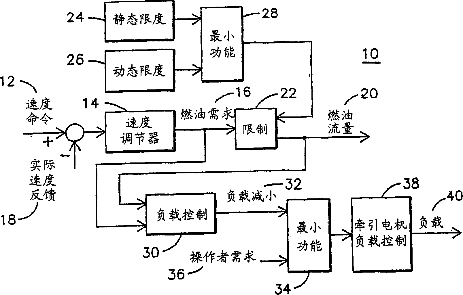
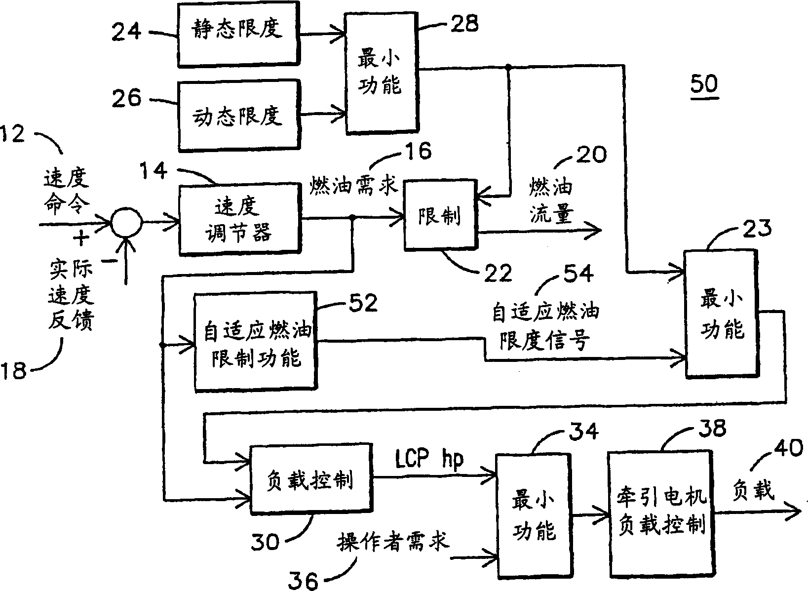
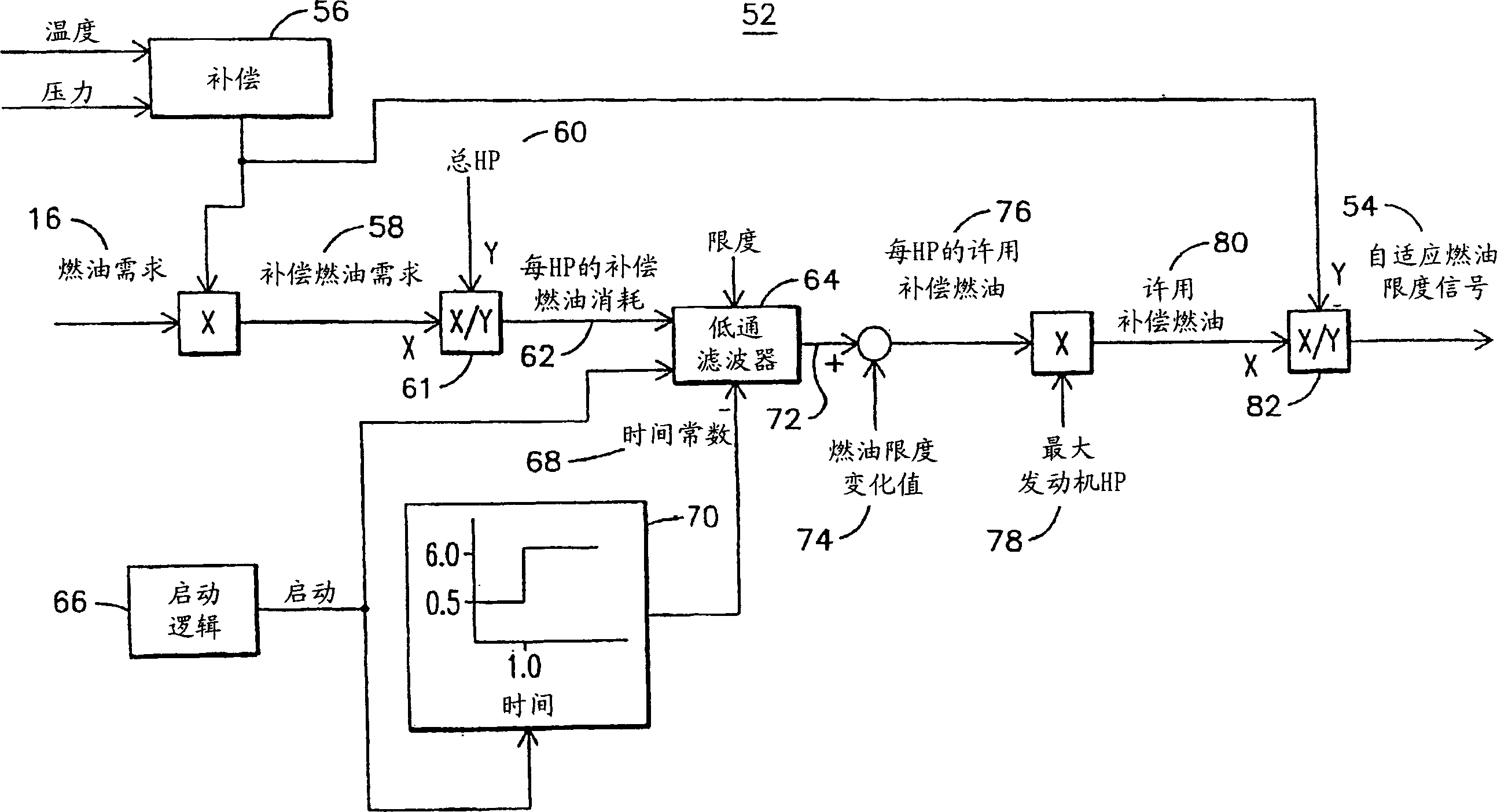
[0013] figure 2 is a block diagram of one embodiment of an improved load control system 50 that may be used in a locomotive or other electric drive system. In this system 50, the speed regulation function 14 and the fuel limit control functions 24, 26, 28 are the same as in the prior art system described in FIG. also, figure 2 The load control system 50 in includes an adaptive fuel limiting function 52 that will reduce the load on the engine, e.g., an engine cylinder or its associated Malfunction of the fuel delivery system. This reduced engine load will indirectly cause fuel flow 20 to drop. Adaptive fuel limit 52 is used to limit fuel flow 20 that may be below the limits imposed by static limit 24 and dynamic limit 26 , thereby further protecting the engine. The adaptive fuel limit function 52 varies the maximum allowable fuel flow in response to the operating history of the engine, and thus in response to a parameter indicative of engine performance versus time, as will...


PUM


Abstract

The invention discloses an adaptive fuel restriction function (52) for protecting an internal combustion engine. The adaptive fuel limit function is a learning function that responds to trends in engine performance parameters such as compensated fuel flow per unit of power produced (62). The engine performance parameter is processed through a low pass filter (64) to allow for changes in the fuel limit signal (54) in response to gradual changes in fuel demand, such as due to engine wear, while responding to gradual changes in fuel demand, such as due to cylinder failure. sudden changes in the fuel limit signal. The difference between the input and output of the low pass filter can be processed to determine the degree of failure (88), thereby providing an alert function other than a learning function.

Description

technical field [0001] The invention relates to a fuel control system for a locomotive internal combustion engine. Background technique [0002] Fuel-injected internal combustion engines are used in many applications including diesel-electric drive systems for railway locomotives. Figure 1 shows a load control system 10 for a diesel generator drive system of a locomotive proposed by the assignee of the present invention. The engine operates at a constant speed which is related to the locomotive operator's initiated power demand (usually referred to as the throttle orifice setting). This speed can be adjusted to a speed command value of 12 by adjusting the fuel supply to the engine. Speed ​​governor 14 generates fuel demand signal 16 based on speed command 12 and actual engine speed feedback signal 18 . During normal operation, fuel demand 16 is directly converted to fuel flow 20 . Under certain conditions, however, the correlation of the fuel quantity 20 to the fuel dema...

Claims


Application Information

Patent Timeline
Patent Type & Authority Applications(China)
IPC IPC(8): F02D41/30F02D31/00F02D41/22F02D41/24
CPCF02D31/007F02D31/009F02D41/22F02D41/2451Y02T10/40F02D41/30
Inventor 阿吉思·K·库马约翰·P·道尔布雷特·D·沃登杰拉尔德·E·莱西
Owner GENERAL ELECTRIC CO
Why Eureka
Try Eureka