Method for mechanical characterization of a metal material

A technology of metal materials and mechanical properties, applied in the field of aviation turbines, which can solve problems such as difficult implementation

Active Publication Date: 2006-08-30
SN DETUDE & DE CONSTR DE MOTEURS DAVIATION S N E C M A
View PDF1 Cites 6 Cited by
  • Summary
  • Abstract
  • Description
  • Claims
  • Application Information

AI Technical Summary

Problems solved by technology

[0014] However, this method is difficult to implement

Method used


Image

  • Method for mechanical characterization of a metal material
  • Method for mechanical characterization of a metal material
  • Method for mechanical characterization of a metal material

Examples


Embodiment Construction

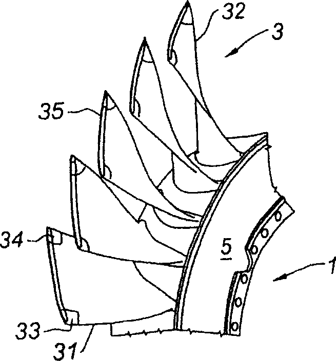
[0033] figure 1 It is a part of the single-blade wheel 1. The blades 3 are radial and distributed around the periphery of the disc 5 . The device is monolithic, that is to say it is either machined from a single blank or manufactured by welding at least some of its elements. In particular, the blades are not attached to the wheel by detachable mechanical means. Areas susceptible to damage are the leading edge 31 , the trailing edge 32 , the leading edge corner 33 , the trailing edge corner 34 and the end line 35 of the wing tip assembled in thin sections forming what is known as a weatherstrip.

[0034] The observed damage depends on the location of the area. For example at the leading edge, trailing edge or wing corner, the damage may be material loss or cracks due to the impact of foreign bodies. At the wing tips, they are often worn due to friction with the engine casing.

[0035] Depending on the area of ​​damage, some material is removed in such a way that the geomet...


PUM


Abstract

A method of repairing a turbomachine blisk having at least one damaged zone by build-up of metal in the damaged zone using a laser build-up welding machine is disclosed. The method includes preparing the damaged zone by machining the damaged zone to obtain a zone of defined profile to be repaired, build-up welding of a start-of-run test piece that includes the defined profile using the laser build-up welding machine, checking geometric and metallurgical quality of the test piece, and build-up welding the zone to be repaired of the blisk using the laser build-up welding machine.

Description

technical field [0001] The invention relates to the field of turbomachines, in particular aeroturbines, with the aim of repairing components such as moving blade disks. Background technique [0002] To meet the increasing performance requirements of engines, single bladed discs or runners, known as "blisks", are now manufactured from titanium alloys for compressors in jet turbine engines. In a conventional rotor, the blades are fixed at their roots and fit into seats on the edge of the disk. Therefore, the disk and the blades are manufactured separately before being assembled into the bladed rotor. In blisks, blades and disks are machined directly from cast blanks, which form a single component. This technology can greatly reduce the total weight of the engine, but also greatly reduce the manufacturing cost. [0003] However, this type of rotor has the disadvantage of being difficult to repair. In operation, compressor blades can be damaged by impact from foreign objects...

Claims


Application Information

Patent Timeline
Patent Type & Authority Applications(China)
IPC IPC(8): B23K31/12
CPCY02T50/671F05D2230/80F01D5/34B23P6/007B23K26/34B23K26/322B23K26/345Y02T50/673F01D5/005B23K26/32B23K35/0244B23K35/325B23K26/342B23K2103/14Y02T50/60Y10T29/49Y10T29/49238Y10T29/49318Y10T29/4932Y10T29/49336
Inventor 博纳德·博伊特斯坦弗尼·迈克尔·科内斯克劳德·安德鲁·查尔斯·派格诺埃里克·克里斯汀·让·皮托
Owner SN DETUDE & DE CONSTR DE MOTEURS DAVIATION S N E C M A
Why Eureka
Try Eureka