Mould for water base pulp gel injection moulding

A technology of gel injection molding and slurry, which is applied in the field of molds for injection molding, which can solve the problems of difficult demoulding, inconvenient use, and poor appearance quality of the green body, and achieve good demoulding quality, convenient processing, and low cost. low effect

Inactive Publication Date: 2006-08-30
HARBIN INST OF TECH
View PDF0 Cites 9 Cited by
  • Summary
  • Abstract
  • Description
  • Claims
  • Application Information

AI Technical Summary

Problems solved by technology

[0003] The purpose of the present invention is to solve the existing water-based slurry gel injection molding, the metal surface is easy to be corroded by the acid-base medium in the water-based slurry, and the green body is easy to be separated from the mold after the slurry is gelled. Adhesion occurs on the metal surface, which leads to difficulty in demoulding the green body, poor appearance quality, and low yield; the use of polymer plastics to make molds has the problems of high manufacturing costs and easy deformation under heating conditions; the use of composite polymer plastics on the surface of metal materials, Due to the problems of high mold production cost, heavy weight, and inconvenient use, a mold for water-based slurry gel injection molding that can prevent the body from sticking to the surface of the mold, easy to demould, good appearance quality, and high yield

Method used


Image

  • Mould for water base pulp gel injection moulding
  • Mould for water base pulp gel injection moulding
  • Mould for water base pulp gel injection moulding

Examples


specific Embodiment approach 1

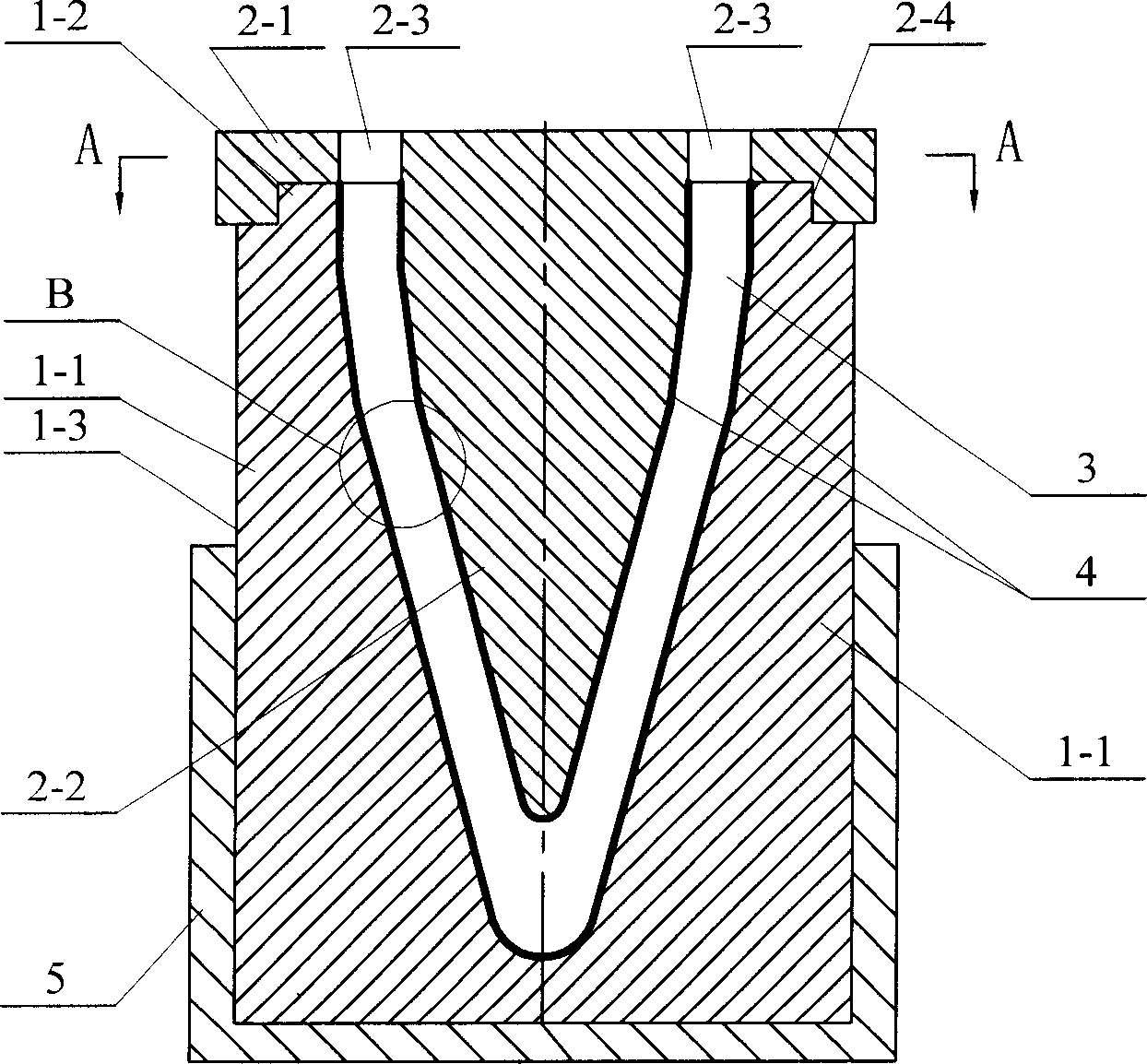
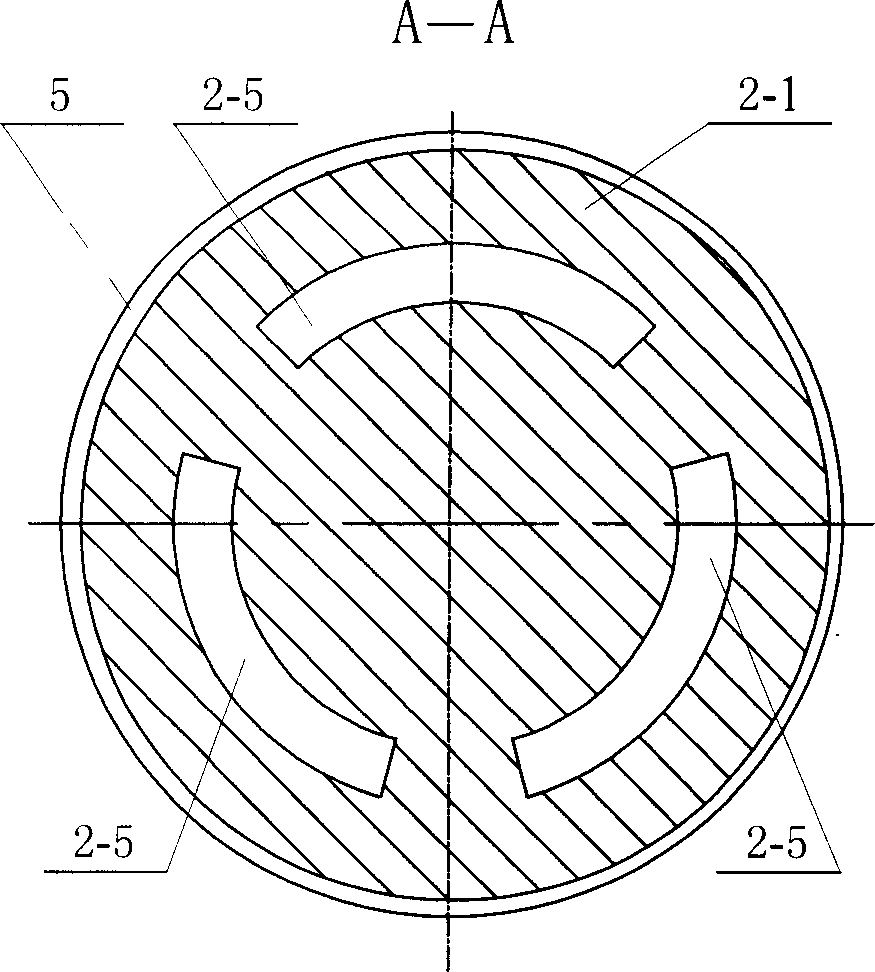
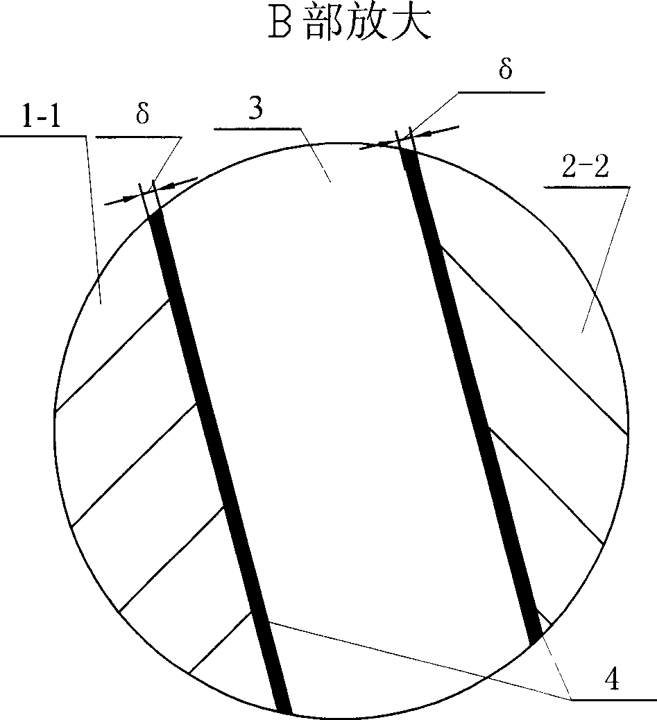
[0007] Specific implementation mode one: combine Figure 1 ~ Figure 3 Describe this embodiment, this embodiment is made up of outer mold, mandrel, anti-adhesive coating 4 and seat cover 5; Described mandrel is made of gland 2-1 and mold core integrated with gland 2-1 2-2, the mold core 2-2 is installed in the inner cavity of the outer mold, and the annular channel 3 is formed by the mold core 2-2 and the inner cavity of the outer mold, and the anti-sticking coating 4 is respectively arranged on the mold core 2 -2 and the surface of the inner cavity of the outer mold, the gland 2-1 is fixedly connected with the outer mold, the gland 2-1 is provided with a slurry inlet 2-3 communicating with the annular channel 3, and the outer The mold is composed of two symmetrically placed half molds 1-1, the lower end of the outer mold is installed in the seat cover 5, the outer end surface of the outer mold is a cylinder 1-3, and the outer mold and the core mold are made of graphite materia...

specific Embodiment approach 2

[0009] Specific implementation mode two: combination figure 1 Describe this embodiment, the difference between this embodiment and specific embodiment one is: the mold core 2-2 of this embodiment and the described outer mold cavity are respectively bullet-shaped, and the mold core 2-2 is contained in the outer mold In the cavity, the annular channel 3 formed by the mold core 2-2 and the inner cavity of the outer mold is in the shape of a bullet. The above-mentioned structure can meet the requirement of making working parts of the ceramic radome.

specific Embodiment approach 3

[0010] Specific implementation mode three: combination figure 1 Describe this embodiment, the upper end of the outer mold of this embodiment is provided with cylindrical protrusion 1-2, and the lower end of described gland 2-1 is provided with the cylindrical protrusion 1-2 of described outer mold. The matching cylindrical inner hole 2-4, the cylindrical protrusion 1-2 of the outer mold is installed in the cylindrical inner hole 2-4 of the gland 2-1, the inner cavity of the outer mold and the mold core 2-2 coaxial. By adopting the above structure, the core mold and the outer mold can be closely combined, thereby ensuring the concentricity of the core mold and the outer mold. Other components and connections are the same as those in the first embodiment.


PUM

PropertyMeasurementUnit
thicknessaaaaaaaaaa
thicknessaaaaaaaaaa
thicknessaaaaaaaaaa

Abstract

The present invention relates to a mould for implementing water base slurry gel injection moulding process. The present invention is characterized by that its core mould is composed of pressure cover and mould core, said mould core and said pressure cover are made into one body. Said mould core is mounted in internal cavity of external mould, said mould core and internal cavity of external mould are formed into an annular channel, the antisticking coating layer is respectively applied on the surface of mould core and internal cavity of external mould, the pressure cover is fixedly connected with the external mould, on the pressure cover is set a slurry inlet communicated with said annular channel. Said external mould is formed from two symmetrically-arranged half-moulds, the lower end of the external mould is placed in the seat cover.

Description

technical field [0001] The present invention relates to a mold for injection molding. Background technique [0002] Gel injection molding method is an effective method for preparing large-scale special-shaped thin-walled components (such as radome, etc.). In the process of gel injection molding, it is necessary to use the mold to carry the slurry, and the green body is obtained through the gelation reaction of the slurry. Currently, the mold materials used are usually metal, plastic, etc. The metal material is used to make the mold, and the metal surface is easily corroded by the acid-base medium in the water-based slurry. After the slurry gels, the green body is easy to stick to the metal surface, resulting in difficulty in demoulding the green body, poor appearance quality, and low yield. low problem. In the test process, polymer plastics (such as polyethylene, polytetrafluoroethylene, nylon, etc.) that are not easy to adhere to the water-based slurry are generally used ...

Claims


Application Information

Patent Timeline
Patent Type & Authority Applications(China)
IPC IPC(8): B29C45/26B29C33/38B29C33/44B29C33/76
Inventor 贾德昌周立忠
Owner HARBIN INST OF TECH
Why Eureka
Try Eureka