

Biomolecule detecting element and method for analyzing nucleic acid using the same
A technology of biomolecules and detection elements, applied in the field of genetic inspection, can solve the problems of increased system size and cost, and achieve the effect of highly accurate and stable detection
- Summary
- Abstract
- Description
- Claims
- Application Information
AI Technical Summary
Problems solved by technology
Method used
Image

Examples
Embodiment approach 1
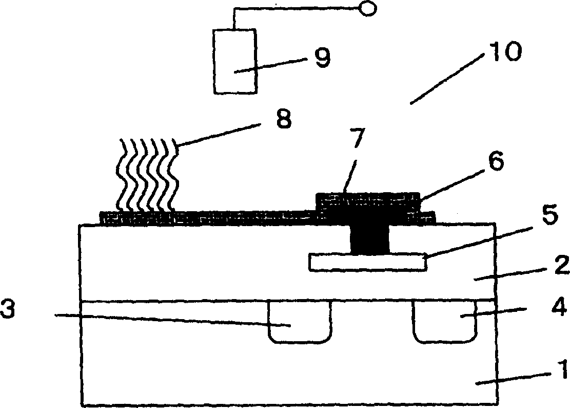
[0049] figure 1 A cross-sectional view schematically showing a biomolecule detection element (biomolecule detection transistor) of the present invention.
[0050] The insulated gate field effect transistor is formed by forming a gate insulating film 2, a source 3, and a drain 4 on the surface of a silicon substrate 1, and disposing a gate on the gate insulating film between the source and the drain. produced by electrode 5. An insulating film is also formed on the surface of the gate electrode 5 so that the gate electrode 5 is embedded in the insulating film 2 . A via hole is formed in the insulating film 2, and a lead-out electrode 6 is formed of a conductive material and placed in electrical contact with the gate electrode 5. A floating electrode 7 is also formed on the gate insulating film and placed in electrical contact with the lead-out electrode 6 . The DNA probe 8 is immobilized on the surface of the floating electrode 7 . The gene transistor thus produced is immer...
Embodiment approach 2
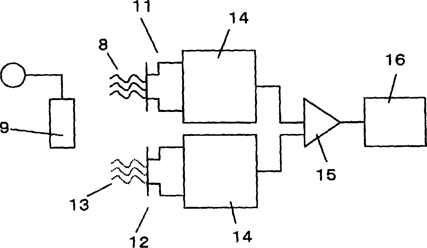
[0065] figure 2 A gene detection system is schematically represented, in which the biomolecule detection transistor according to the first embodiment is used. In this system, in addition to figure 1 In addition to the biomolecule detection transistor 11 shown, a reference transistor 12 is used, and a differential measurement is performed using both transistors.
[0066] On the gate surface of the biomolecule detection transistor is immobilized a DNA probe 8 whose base sequence is complementary to that of a target gene in the sample. On the other hand, on the gate surface of the reference transistor, a DNA probe 13 whose base sequence is different from the complementary base sequence of the target gene is immobilized. In order to stably measure the surface potential of the biomolecule detection transistor and the reference transistor, a reference electrode 9 is provided as a reference for potential measurement. The surface potentials of the biomolecule detection transistor ...
Embodiment approach 3
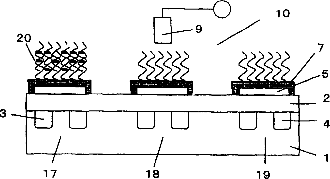
[0070] image 3 Schematically expressing the use of figure 1 A cross-sectional view of another example of a measurement system for the shown biomolecule detection transistor. In this measurement system, three FETs are integrated. The first biomolecule detection transistor 17 is used to detect the first target gene. A second transistor 18 is used to detect the second target gene. The third transistor 19 is used as the reference transistor. On the gate electrodes of the first and second biomolecule detection transistors, DNA probes having base sequences complementary to the first and second genes are immobilized, respectively. A DNA probe having a base sequence different from the complementary base sequence of the first or second gene is immobilized on the surface of the gate electrode of the reference reference FET.
[0071] image 3The state is such that a sample solution containing only the first gene has been introduced into the above-mentioned integrated transistor, a...
PUM
 Abstract
Description
Claims
Application Information