Cold cathode tube device

A cold-cathode tube and cold-cathode technology, applied in discharge tubes, optics, instruments, etc., can solve the problems that cold-cathode tubes cannot obtain sufficient brightness and reduce lamp brightness, and achieve the goal of improving work efficiency, sufficient brightness, and simple assembly operations Effect

Inactive Publication Date: 2006-09-06
大和灯具工业股份有限公司 +1
View PDF2 Cites 0 Cited by
  • Summary
  • Abstract
  • Description
  • Claims
  • Application Information

AI Technical Summary

Problems solved by technology

Generally speaking, the brightness of cold-cathode tubes tends to decrease in low-temperature environments. When cold-cathode tubes are used in low-temperature facilities such as freezers and refrigerated warehouses, there is a problem that cold-cathode tubes cannot obtain sufficient brightness.

Method used


Image

  • Cold cathode tube device
  • Cold cathode tube device
  • Cold cathode tube device

Examples


Embodiment Construction

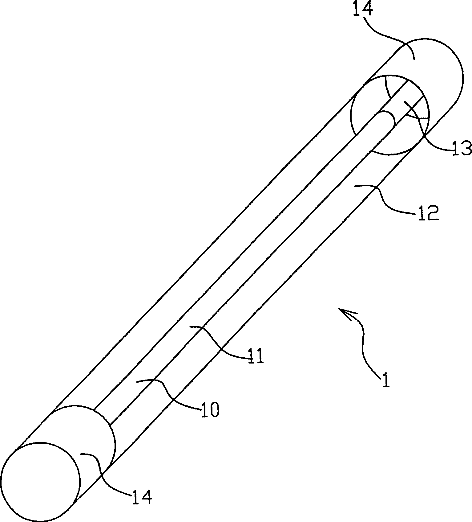
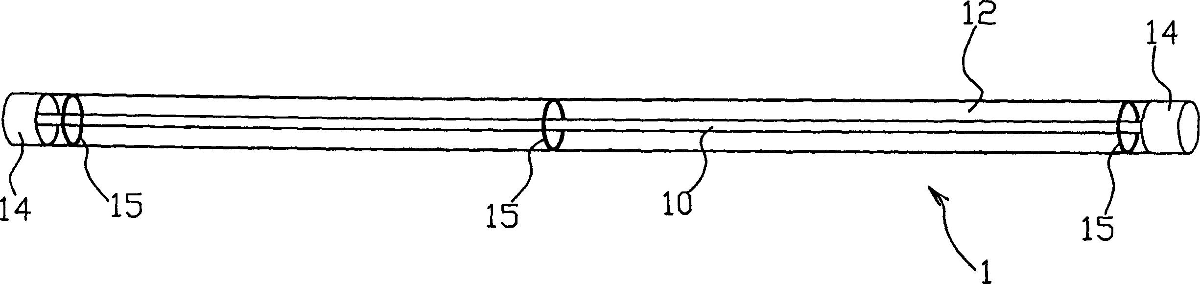
[0037] figure 1 , figure 2 It is a three-dimensional schematic view and a side view of the first embodiment of the cold cathode tube device of the present invention. like figure 1 As shown, the cold-cathode tube device 1 of the present embodiment has a cold-cathode tube 10, electrodes 13 for the purpose of applying a voltage are formed at both ends thereof, and a light-transmitting support tube 12 has a diameter larger than that of the cold-cathode tube 10. , in order to fix the above-mentioned cold cathode tube 10 inside it, and two support tube electrodes 14 are respectively arranged at the two ends of the light-transmitting support tube 12, and the two support tube electrode parts 14 are connected with the cold cathode tube 10 respectively. The two electrodes 13 are connected together.

[0038] When manufacturing the cold cathode tube 10 of the cold cathode tube device 1 with such a double structure, rare gases such as argon and neon and a very small amount of mercury a...


PUM

PropertyMeasurementUnit
diameteraaaaaaaaaa

Abstract

The present invention discloses a cold cathode tube device. It contains at least one cold cathode tube whose two ends respectively forming one electrode, light permeability support tube whose diameter being greater than that of cold cathode tube for holding cold cathode tube, two support tube electrode portion respectively set two ends of light permeability support tube to make it respectively forming electrical property connection with electrode of cold cathode tube. The present invention can prevent breakage in installation and replacement operation and obtain sufficient luminescence brightness.

Description

technical field [0001] The invention relates to a cold-cathode tube device, in particular to a cold-cathode tube device which can improve the strength and low-temperature characteristics of the cold-cathode tube. Background technique [0002] Generally, cold-cathode tubes are used in devices that require light sources, such as backlights for liquid crystal display devices. Such cold cathode tubes used in liquid crystal display devices etc. are coated with phosphor on the inner wall of a slender glass tube, and inert gas (argon, etc.) and mercury are sealed in the glass tube. Secondly, the power source applies a high voltage between the electrodes at both ends of the glass tube through an external wire to start the discharge, and the vaporized mercury will be excited to generate ultraviolet rays (mainly at a wavelength of 253.7nm) under the impact of electrons or atoms enclosed in the gas. The ultraviolet light excites the phosphor and converts it into a luminous color (visi...

Claims


Application Information

Patent Timeline
Patent Type & Authority Applications(China)
IPC IPC(8): H01J5/50H01J61/30H01J61/00G02F1/13357G02F1/1335
Inventor 牧野周一藤井乔
Owner 大和灯具工业股份有限公司
Why Eureka
Try Eureka