Power factor correcting device

A power factor correction, positive AC technology, applied in output power conversion devices, sustainable manufacturing/processing, electrical components, etc., can solve the problems of delay capacitor C1 charging time, no structure, inconvenience, etc., to improve the choke coil and inductance value, avoid choke coil and inductance value, increase the effect of conduction time

Inactive Publication Date: 2006-09-06
NEWTON POWER
View PDF0 Cites 0 Cited by
  • Summary
  • Abstract
  • Description
  • Claims
  • Application Information

AI Technical Summary

Problems solved by technology

[0007] However, the passive PFC circuit designed with this architecture must increase the choke coil and inductance value of the inductor L1 as much as possible to increase the conduction time of the inductor L1 and limit the operating current I on the inductor L1. L1 The peak current, so as to in turn control the charging current of capacitor C1
However, if the choke coil and inductance of the inductor L1 are increased, the charging time of the capacitor C1 will be delayed, so that the capacitor C1 cannot obtain a complete charging process, thus affecting the DC voltage V output by the passive PFC circuit out1
In addition, if this passive PFC circuit is to be applied to a high-power power supply circuit, the choke coil and inductance value of the inductor L1 cannot be increased.
[0008] It can be seen that the above-mentioned existing power factor correction circuit obviously still has inconvenience and defects in structure and use, and needs to be further improved urgently.
In order to solve the problems existing in the power factor correction circuit, the relevant manufacturers have tried their best to find a solution, but no suitable design has been developed for a long time, and the general products do not have a suitable structure to solve the above problems. Obviously, it is a problem that relevant industry players are eager to solve.

Method used


Image

  • Power factor correcting device
  • Power factor correcting device
  • Power factor correcting device

Examples


Embodiment Construction

[0065] In order to further explain the technical means and effects that the present invention adopts to achieve the intended purpose of the invention, the specific implementation, structure, features and effects of the power factor correction device proposed according to the present invention will be described below in conjunction with the accompanying drawings and preferred embodiments. , as detailed below.

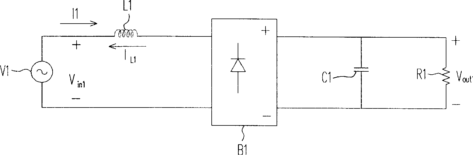
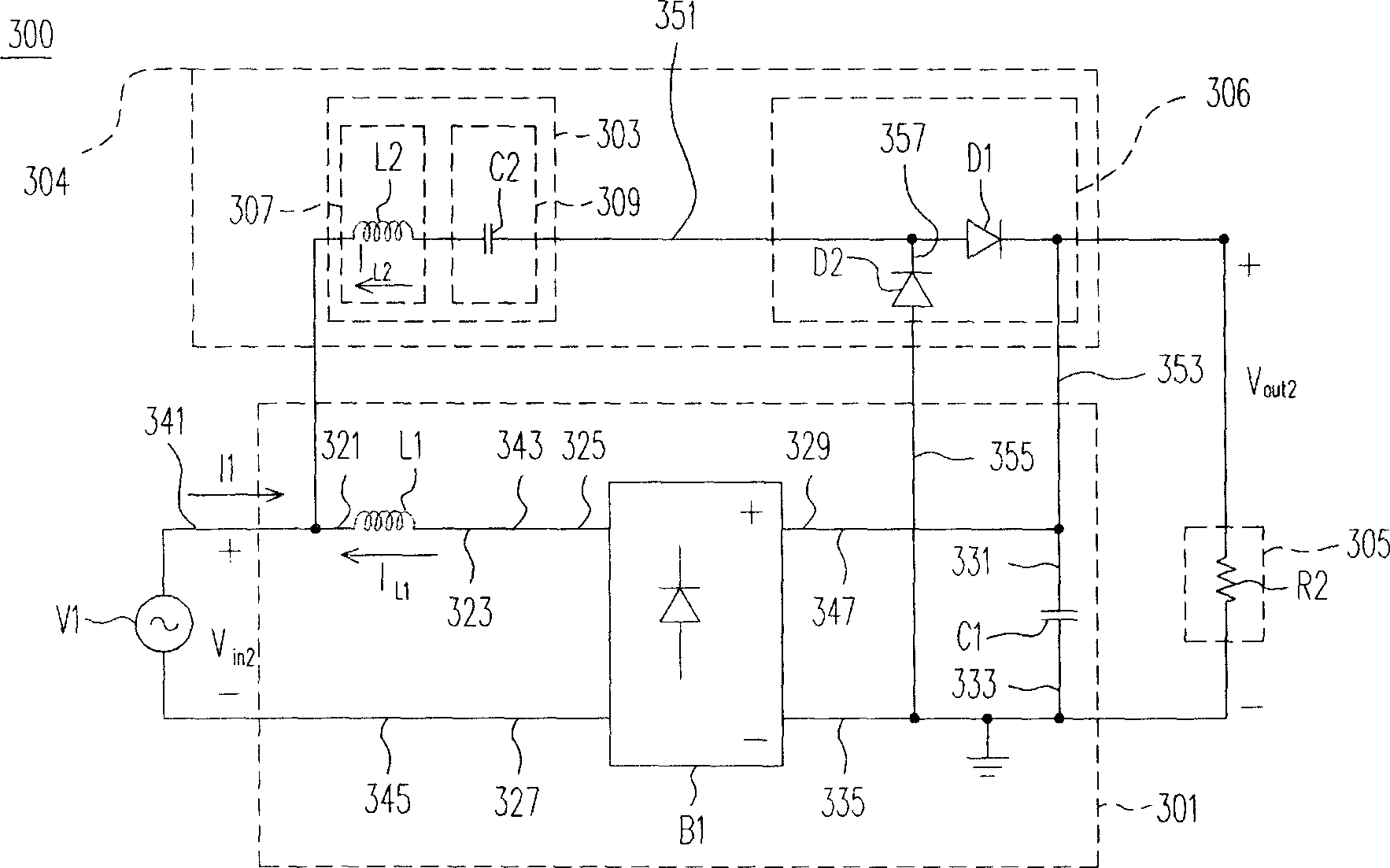
[0066] The biggest feature of the power factor correction (Power Factor Correction, PFC) device proposed by the present invention is that a group of PFC auxiliary circuits are coupled between the input end and the output end of the general AC-DC conversion circuit, so as to increase the input The conduction time of the current and limit the peak value of the input operating current to avoid raising the choke coil and inductance value of the inductor.

[0067] see image 3 As shown, the symbol 300 is a circuit diagram of a complete PFC device according to the present inv...


PUM


Abstract

The present invention refers to power-factor correction device, consisting of ac / dc conversion circuit and PFC auxiliary circuit. Said device couples a group of auxiliary circuit between input end and output and output end of ac / dc conversion circuit, for increasing current conducting time and limiting working current peak value without the need to raise inductor choke and inductor value.

Description

technical field [0001] The invention relates to a power factor correction device, in particular to a passive power factor correction device capable of improving power factor. Background technique [0002] Power Factor (Power Factor) represents the relationship between effective power and total power consumption, that is, the ratio of effective power divided by total power consumption. Basically, the power factor can measure the degree to which electricity is effectively utilized. When the power factor value is larger, it represents the higher the power utilization rate. The operating principle of the Power Factor Correction (PFC) circuit on the power supply is to control and adjust the time and waveform of the AC current input to make it as consistent as possible with the DC voltage waveform, so that the power factor approaches 1. This is important for electronic equipment whose power requirements are large enough that otherwise the power equipment system may consume more p...

Claims


Application Information

Patent Timeline
Patent Type & Authority Applications(China)
IPC IPC(8): H02M1/12H02M1/14
CPCY02P80/10
Inventor 邓柏村
Owner NEWTON POWER
Why Eureka
Try Eureka