Method for deciding margin of single line blade of axial flow compressor

A technology for axial flow compressors and compressors, which is applied in the direction of blade support components, mechanical equipment, engine components, etc., to achieve the effect of easy application and intuitive understanding

Active Publication Date: 2006-09-13
中科思道(南京)储能技术有限公司
View PDF0 Cites 1 Cited by
  • Summary
  • Abstract
  • Description
  • Claims
  • Application Information

AI Technical Summary

Problems solved by technology

[0004] The purpose of the present invention is to overcome the blindness of margin performance control in the existing axial flow compressor design process, based on the understanding of the factors affecting the margin of axial flow compressor, through the appropriate devel

Method used


Image

  • Method for deciding margin of single line blade of axial flow compressor
  • Method for deciding margin of single line blade of axial flow compressor
  • Method for deciding margin of single line blade of axial flow compressor

Examples


Embodiment 1

[0028] For a compressor blade, the process of designing to achieve the margin target includes the following steps:

[0029] 1) Interpret the succession of each section of the blade to reach the stall directly from the calculation results of the three-dimensional flow field;

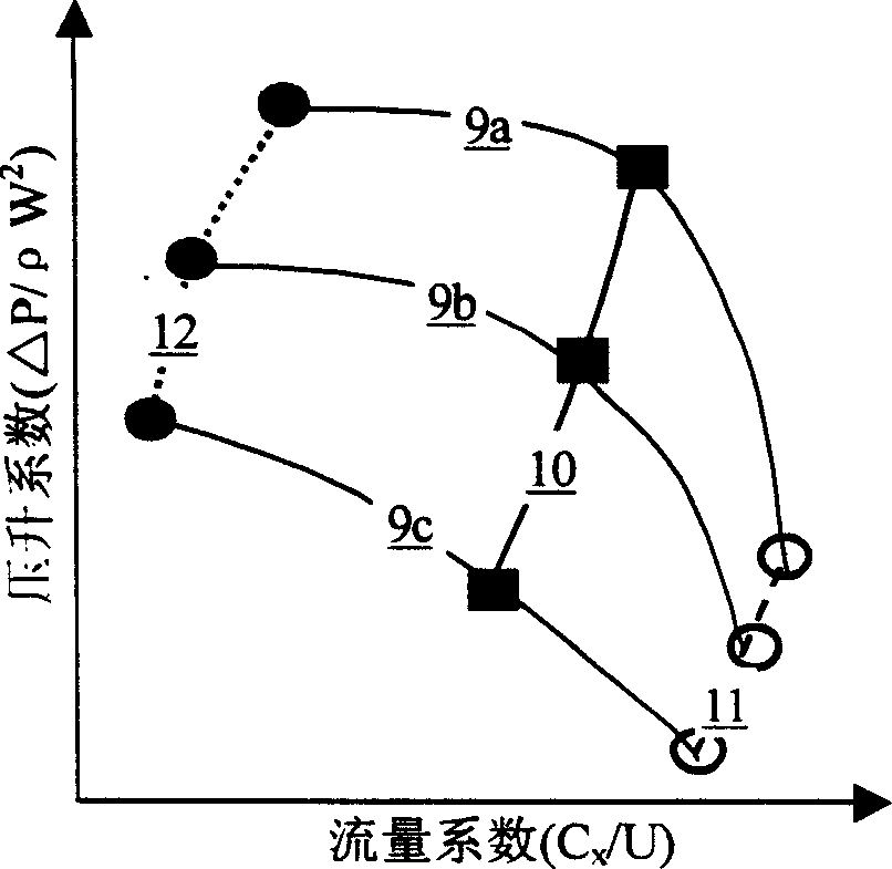
[0030] 2) The flow-load characteristics of each section are plotted in the same figure; according to the full three-dimensional flow calculation results of the entire blade design condition, determine image 3 The positions of the design points on the flow-load characteristic line of each section shown in , are also shown in Figure 4 ,Right now Figure 4 Shown in curve 13;

[0031] 3) Calculate the full three-dimensional flow field to the near-stall point for the entire blade, and then determine the actual positions of the operating points of each section of the entire blade near the stall point, as Figure 4 point on curve 15;

[0032] 4) if Figure 7 As shown, it represents the calculation result ...

Embodiment 2

[0038] For a compressor blade, the process of designing to achieve the margin target includes the following steps:

[0039] 1) The compressor blade is regarded as an infinite number of small compressors with infinitely small height matched in the span direction, and each small compressor has a corresponding flow-load characteristic line, such as image 3 Shown in the curves 9a, 9b, 9c; the maximum flow state corresponds to the line 11 ( image 3 is the point on the dotted line 11), in image 3 The right end of each flow-load characteristic line in is represented by a hollow circle; the minimum flow state corresponds to the near-stall condition line 12 ( image 3 is on the dotted line 12), in image 3 The left end of each flow-load characteristic line in , is represented by a solid circle; a middle flow point corresponds to the design condition line 10 ( image 3 is the solid line 10), in image 3 is represented by a solid rectangular box on each flow-load characteristic li...

Embodiment 3

[0047] For a compressor blade, the process of designing to achieve the margin target includes the following steps:

[0048] 1) Interpret the succession of each section of the blade to reach the stall directly from the results of the three-dimensional calculation of the fluid;

[0049] 2) The flow-load characteristics of each section are plotted in the same figure, and according to the full three-dimensional flow calculation results of the entire blade design condition, determine image 3 The positions of the design points on the flow-load characteristic line of each section shown in , are also shown in Figure 4 ,Right now Figure 4 Shown in curve 13;

[0050] 3) Use the full three-dimensional flow calculation for the entire blade to the near-stall point, and then determine the actual positions of the operating points of each section of the entire blade near the stall point, as Figure 4 point on curve 15;

[0051] 4) if Figure 7 As shown, it represents the calculation r...


PUM


Abstract

The invention discloses a method for making vane of an axial flow type air compressor have given tolerance, mainly comprising the steps as follows: taking flow-load characteristics of root, middle and tip sections or more sections of the vane and drawing them in the same diagram, and determining positions of design points on the flow-load characteristic line of each section according to the full 3D flow calculated results of design working conditions of the whole vane; making full 3D flow calculation on the whole vane to near stall points, and then determining actual positions of working points of each section as the whole vane is at the near stall points; judging which section tolerance or which ones are not enough, and adopting corresponding measures comprising moving this/these sections forward and in the rotating direction and modifying vane shapes of this/these sections to make pneumatic load barycenters of this/these sections move backward. And it implements tolerance control by physical essence of influencing tolerance of single row of vanes of a fan/air compressor.

Description

technical field [0001] The invention relates to a design method of an axial flow compressor blade, in particular to a method for making the axial flow compressor blade have a given margin performance. Background technique [0002] The known axial flow compressor is an important component widely used in aviation, aerospace, navigation, energy, chemical industry and other fields, such as figure 1 As shown, it is composed of a hub 1, a casing 2 and a plurality of rows of blades contained therein at a distance, wherein the blades include rotor blades 3 rotating around an axis and stator blades 4 fixed on the casing 2 . Such as figure 2 As shown, all blades are formed by stacking primitive cascades 5 along the center of gravity stacking line 6 in the span direction, and the leading edge 7 and trailing edge 8 of the blades are formed by stacking the front and rear parts of the cascades, as shown in figure 1 , 2 As shown, the pressure of the working fluid gas is increased after...

Claims


Application Information

Patent Timeline
IPC IPC(8): F01D5/14
Inventor 季路成陈江
Owner 中科思道(南京)储能技术有限公司
Why Eureka
Try Eureka