

Hydro-float solid-liquid magnetic fluid generating technology device
A magnetic fluid power generation and technical device technology, applied in the direction of electromechanical devices, electrical components, etc., can solve the problems such as the rare application of hydraulic buoyancy power generation, and achieve the effects of improving the power supply quality of the power grid, convenient maintenance, and simple structure
- Summary
- Abstract
- Description
- Claims
- Application Information
AI Technical Summary
Problems solved by technology
Method used
Image

Examples
Embodiment Construction
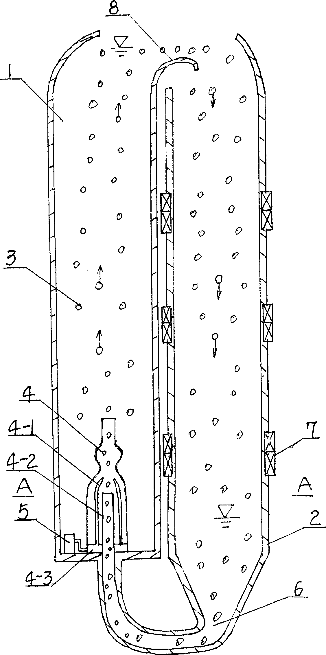
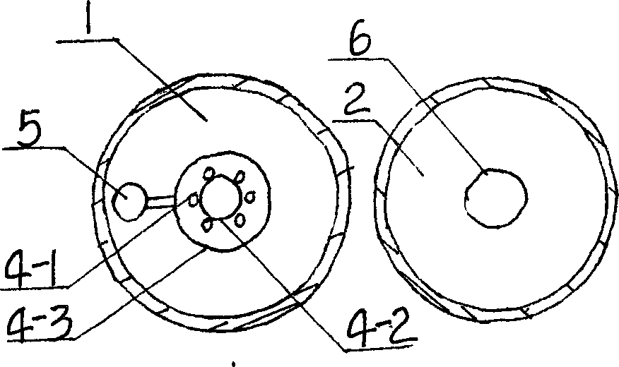
[0017] exist figure 1 , figure 2 Among them, A vertical cylindrical tube (1) is built by reinforced concrete, is the structure shape of vertical cylindrical tube, and it is filled with water. B upright cylindrical tube (2) is made by glass fiber reinforced plastics, and the top is the upright cylindrical tube structural shape, and the bottom is the horn shrinkage shape, is filled with a certain amount of water in its bottom. The magnetic particles (3) are magnetic hollow spheres, and their specific gravity is less than 1. The ejector (4) is installed at the bottom of the upright cylinder (1) of A, and there are 6 ejector nozzles (4-1), all of which are arranged around the ejector suction pipe (4-2), and the heads of the nozzles are inclined to the center , 6 ejector nozzles (4-1) are all communicated with the ejector high-pressure water cavity (4-3). The ejector suction pipe (4-3) is arranged vertically and communicates with the magnetic particle inlet pipe (6). The subme...
PUM
 Abstract
Description
Claims
Application Information