Auditory localization method

A technology of sound source localization and position vector, applied in the direction of frequency/direction characteristic device, etc., can solve the problem of poor sound source localization accuracy

Inactive Publication Date: 2006-09-13
HUAWEI TECH CO LTD +1
View PDF0 Cites 44 Cited by
  • Summary
  • Abstract
  • Description
  • Claims
  • Application Information

AI Technical Summary

Problems solved by technology

[0041] The object of the present invention is to provide a sound source localization method to overcome the disadvantage of poor sound source localization accuracy existing in the two-dimensional space localization of the sound source in the prior art

Method used


Image

  • Auditory localization method
  • Auditory localization method
  • Auditory localization method

Examples


Embodiment Construction

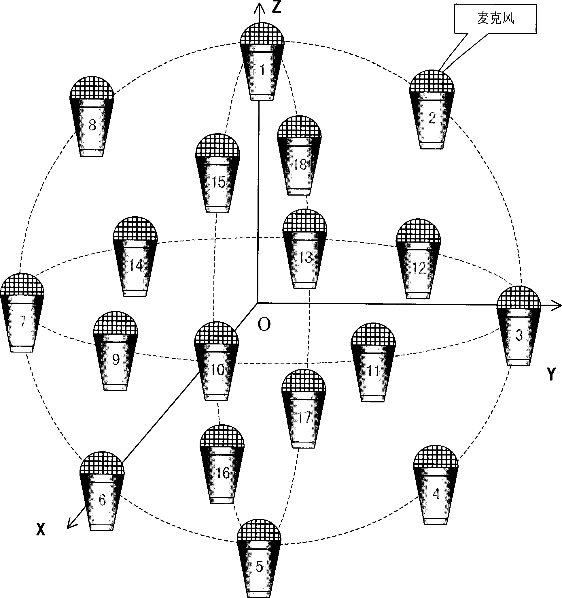
[0110] In the actual sound pickup environment of the microphone, the position of the sound source may change in the three-dimensional space due to the speaker’s walking, sitting up, etc. If the three-dimensional sound source localization can be performed during the sound source localization, the microphone’s accuracy can be improved. Accurate sound source positioning, so that the pickup system can accurately track the sound source, and improve the voice communication quality of the pickup system.

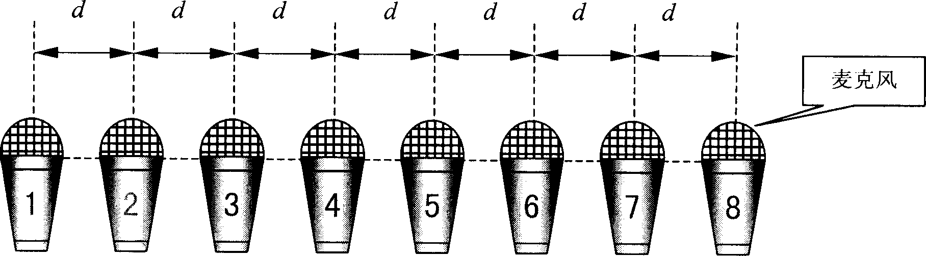
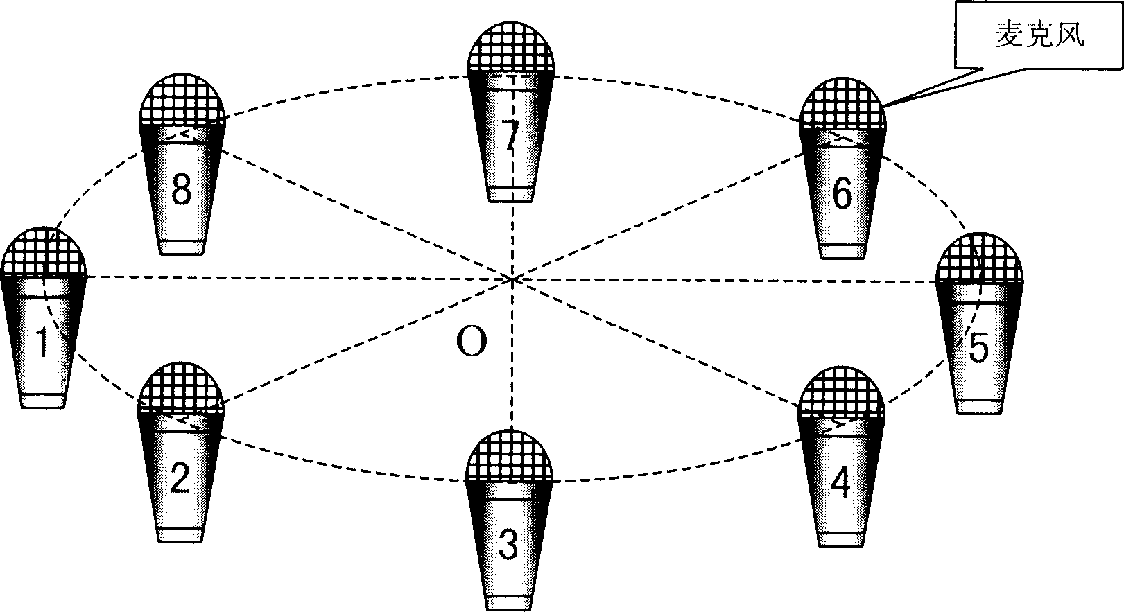
[0111] Therefore, the core of the present invention is: according to the predetermined three-dimensional space coordinates, the three-dimensional space within the range of sound pickup is divided into several space search points, and the three-dimensional search position vectors of each space search point are respectively determined according to the predetermined frequency points, according to the The three-dimensional search position vector and the sound source signal of each space ...


PUM


Abstract

This invention provides a sound source locating method including: dividing a 3-D space into several spacial searching points in a pick-up sphere based on a pre-designed 3-D spacial coordinate, determining the research position vector of each spacial search point based on the pre-designed frequency points to determine a 3-D spacial spectrum matrix of the frequency points to determine the 3-D position information of the sound source based on said matrix.

Description

technical field [0001] The invention relates to audio processing technology in the technical field of multimedia communication, in particular to a sound source localization method. Background technique [0002] In the microphone-based sound pickup system, the sound source localization technology can determine the sound of interest, so that the sound pickup system can perform sound denoising, sound source tracking, speech extraction and separation, etc. on the received signal. Accurate sound source localization can effectively improve the quality of voice communication in noisy backgrounds. [0003] Traditional sound pickup tools are generally a single isolated microphone. A single microphone will receive all sounds including noise within its pickup range, that is, the signal received by a single microphone is a mixed signal composed of environmental noise and sounds from multiple sound sources. [0004] A single microphone cannot adaptively align and track the speaker of i...

Claims


Application Information

Patent Timeline
Patent Type & Authority Applications(China)
IPC IPC(8): H04R1/40
Inventor 邵怀宗居太亮林静然彭启琮余水安
Owner HUAWEI TECH CO LTD
Why Eureka
Try Eureka