Thermosyphon and method of manufacturing the same

A thermosiphon and outer tube technology, applied in heating methods, household heating, sustainable buildings, etc., can solve the problems of decreased heating efficiency or cooling efficiency, high manufacturing cost of thermosiphon, and low qualified rate of cover materials, etc. Achieve the effect of reducing heat transfer loss, simple fixing operation, and cost reduction

A thermosiphon and outer tube technology, applied in heating methods, household heating, sustainable buildings, etc., can solve the problems of decreased heating efficiency or cooling efficiency, high manufacturing cost of thermosiphon, and low qualified rate of cover materials, etc. Achieve the effect of reducing heat transfer loss, simple fixing operation, and cost reduction

CN1833154AInactive Publication Date: 2006-09-13武原力

Image

  • Thermosyphon and method of manufacturing the same
  • Thermosyphon and method of manufacturing the same
  • Thermosyphon and method of manufacturing the same

Examples


Embodiment Construction

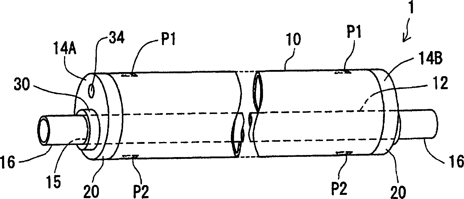
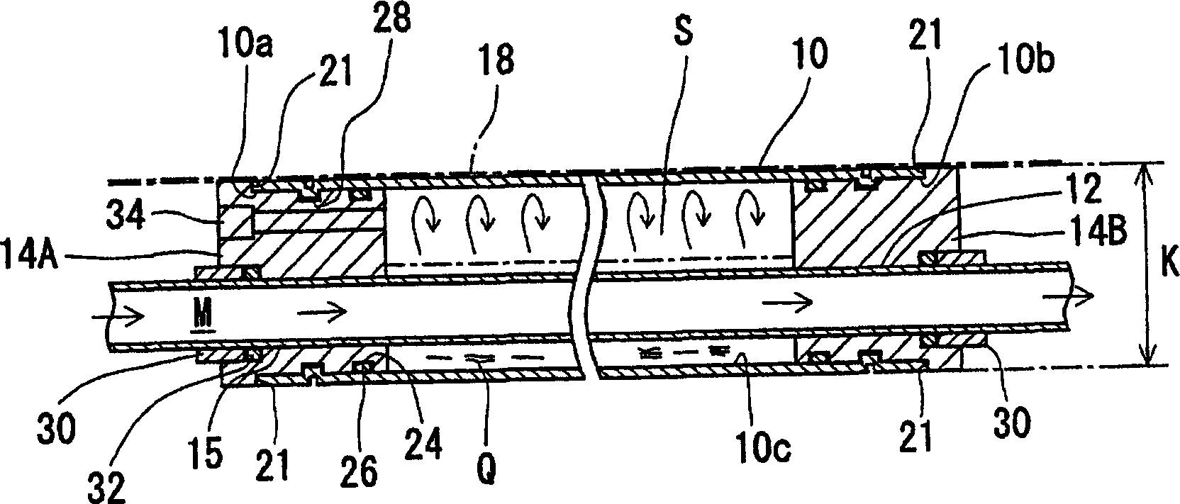
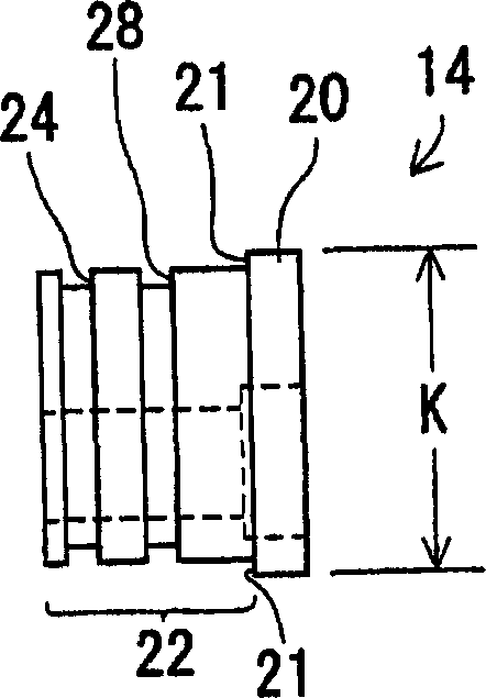
[0037] Hereinafter, embodiments of the thermosiphon device of the present invention will be described with reference to the drawings, together with a method of manufacturing the same. In the thermosiphon device of the present invention, the inner pipe used for the flow of the heat source fluid M is penetrated in the outer pipe, and the working fluid (medium) in the outer pipe is subjected to high-speed evaporation and condensation cycles by using the warm and cold heat from the heat source fluid. Heat, heat transfer device for heating or cooling around the outer tube. In particular, in this embodiment, the thermosiphon device is applied to, for example, a device for underground heating that is installed under the ground of a building with multiple connections in a horizontal type, and that supplies warm heat source fluid from a heat source device to heat the room. The situation is described as an example.

[0038] Figure 1 to Figure 8 shows the thermosiphon device 1 of this...


PUM


Abstract

A thermosyphon formed in a simple structure, enabling an increase in heat transfer efficiency for transferring heat from the thermosyphon to the outside, and manufacturable at low cost and a method of manufacturing the thermosyphon. The double tube type thermosyphon is formed in a single and constant outside diameter size of cylindrical shape having an outer tube (10) and plug bodies (14). The outer tube (10) and the plug bodies (14) are formed in the constant outside diameter (K) size so as to come into contact simultaneously with one plane put on the upper outer surface thereof. Thus, for example, when the syphon is installed under a floor, the syphon is continuously fitted to an upper heat transfer plate in the longitudinal direction to reduce heat transfer loss and increase the heat transfer efficiency. Also, the yielding of material can be increased by reducing cut-out portions.

Description

technical field [0001] The present invention relates to a thermosiphon device and a manufacturing method thereof, in particular to a double-tube type thermosiphon device and a manufacturing method thereof, in which an inner pipe used for heat source fluid circulation is penetrated in an outer pipe serving as a main pipe. Background technique [0002] For heat exchange equipment such as heat pumps, which have the characteristic that the smaller the temperature difference between the heat exchange fluids, the lower the heat exchange efficiency, recently, thermosiphon devices that can transfer a large amount of heat with a small temperature difference by using condensation and evaporation phase changes are gradually being developed. Practical. Among them, the inner tube for the circulation of the heat source fluid is passed through the outer tube, for example, a structure in which cold and warm heat is transferred horizontally is excellent in practicality and attracts attention...

Claims


Application Information

Patent Timeline
13 Sep 2006
Publication
CN1833154A
IPC
F28D15/02; F24D3/14
CPC
F24D3/14; F28D15/0233; Y02B30/00; F28D15/02
Inventors
武原敏夫