Burning device
A technology of a combustion device and a combustion basket, which is applied in the directions of burners, combustion methods, combustion types, etc., can solve problems such as cost increase and increase in cost, and achieve the effects of realizing cost, reducing man-hours, and easy assembly.
- Summary
- Abstract
- Description
- Claims
- Application Information
AI Technical Summary
Problems solved by technology
Method used
Image

Examples
Embodiment Construction
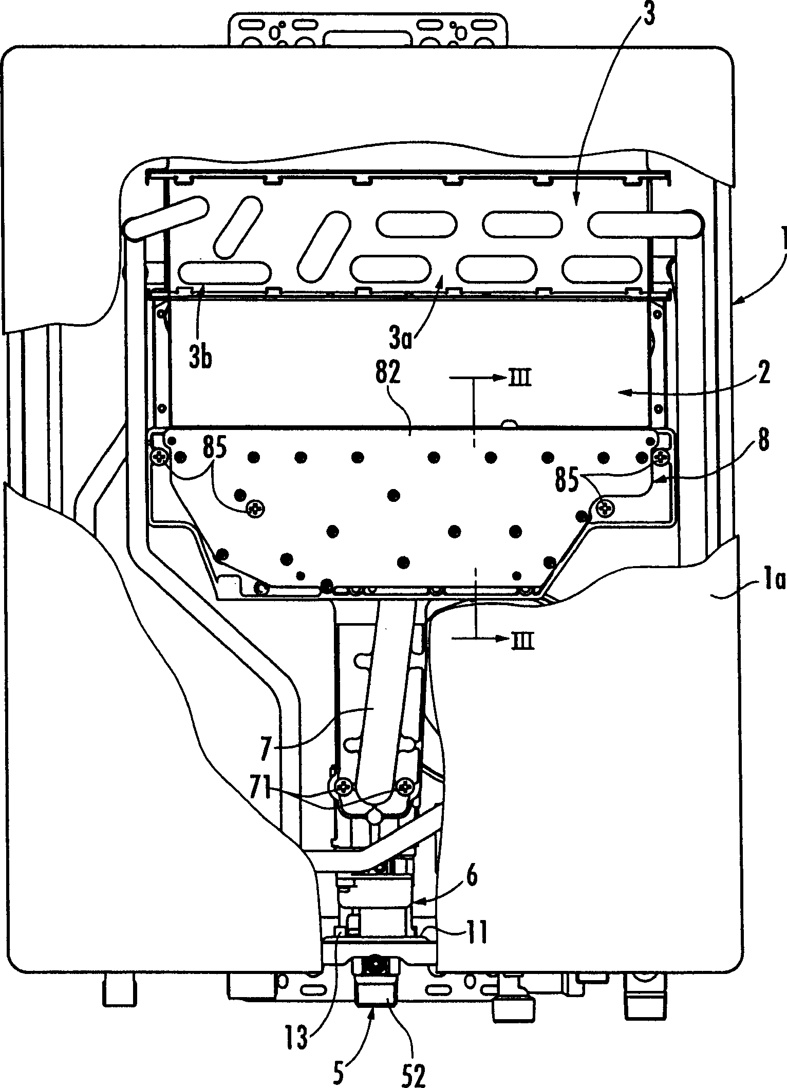
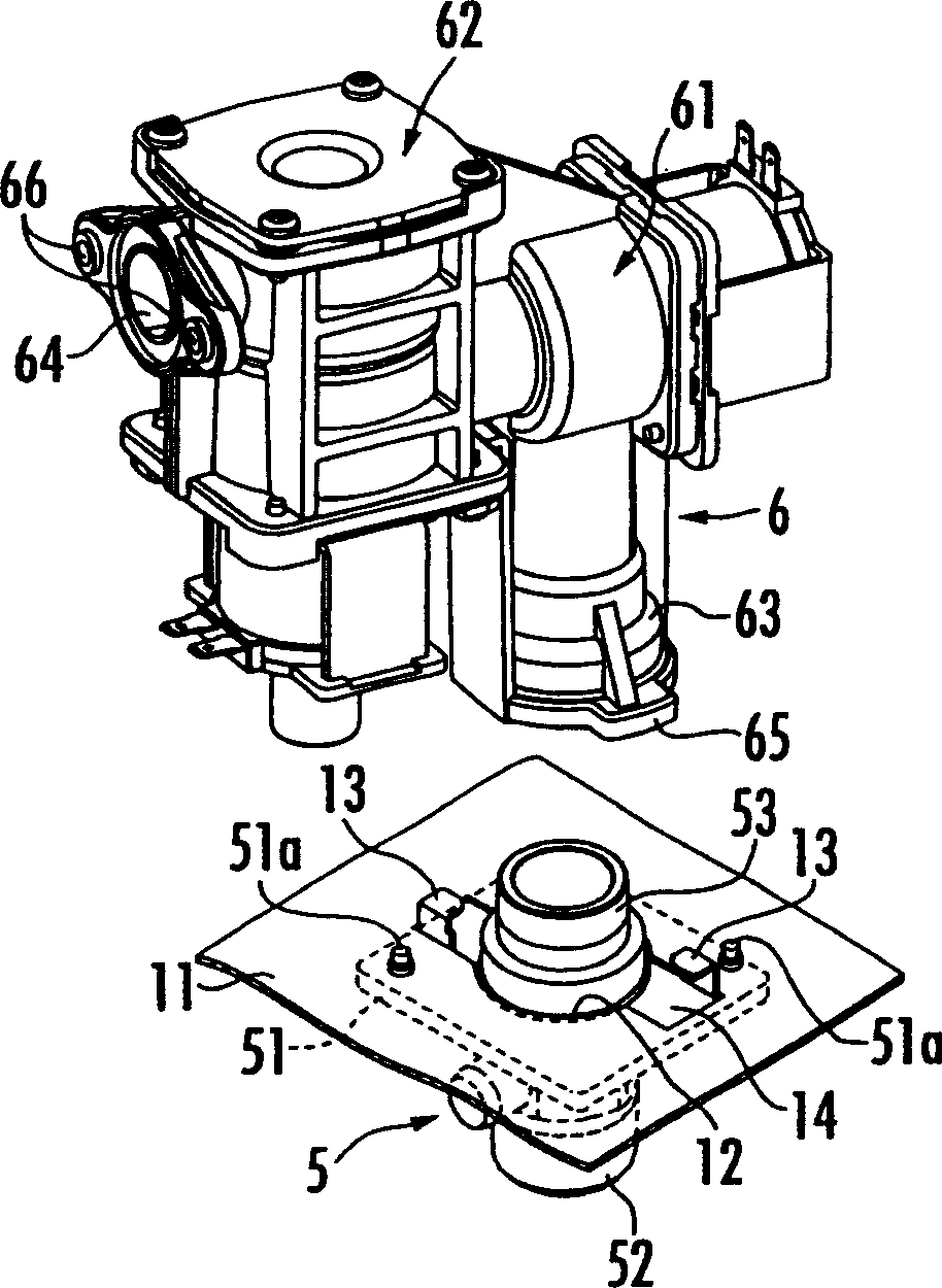
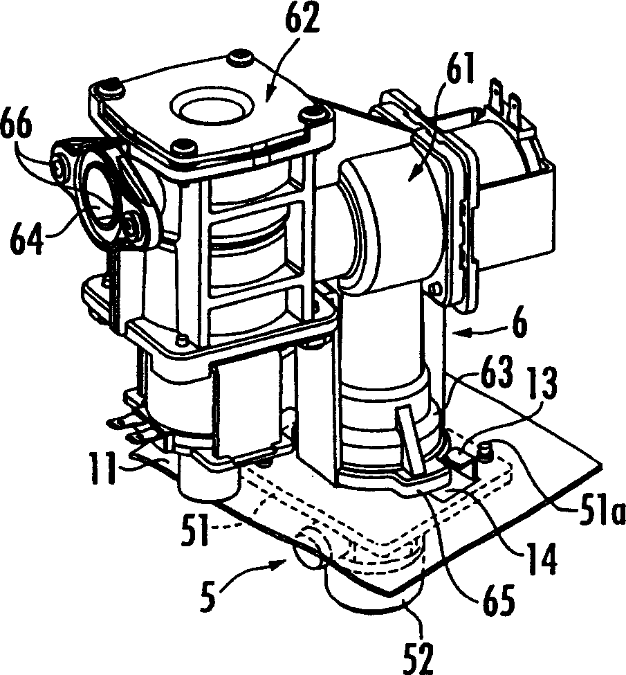
[0018] refer to figure 1 , 1 denotes an external box of a water heater as a combustion device, and the front of the external box 1 is constituted by a detachable front panel 1a. Inside the external box 1, a combustion basket 2 and a heat exchanger 3 on the upper side of the combustion basket 2 are disposed. In the combustion basket 2, a plurality of burners 4 arranged side by side in the transverse direction as the longer direction thereof (refer to image 3 , Figure 4 ). Moreover, gas is installed on the lower surface of the lower plate portion 11 of the external box body 1 from the joint member 5 for gas piping, and passes through the valve unit 6, the gas piping member 7, and the multiple joint installed on the combustion basket 2. 8 and supply these burners 4 . Moreover, the heat exchanger 3 is provided with the hot water supply heat exchange part 3a and the bath water additional heating heat exchange part 3b. Furthermore, the burner 4 divided into the hot water supp...
PUM
 Abstract
Description
Claims
Application Information
 - R&D
- Intellectual Property
- Life Sciences
- Materials
- Tech Scout
- Unparalleled Data Quality
- Higher Quality Content
- 60% Fewer Hallucinations
Browse by: Latest US Patents, China's latest patents, Technical Efficacy Thesaurus, Application Domain, Technology Topic, Popular Technical Reports.
© 2025 PatSnap. All rights reserved.Legal|Privacy policy|Modern Slavery Act Transparency Statement|Sitemap|About US| Contact US: help@patsnap.com