
Arc length control method for impulse arc welding

An arc length and pulse arc technology, applied in arc welding equipment, welding equipment, manufacturing tools, etc., can solve problems such as instability of feedback control system, and achieve the effect of improving arc length controllability and high precision

Active Publication Date: 2006-09-27
DAIHEN CORP
View PDF2 Cites 46 Cited by
  • Summary
  • Abstract
  • Description
  • Claims
  • Application Information

AI Technical Summary

Problems solved by technology

However, in this method, the feedback control system tends to become unstable, and there is a limit

Method used


Image

  • Arc length control method for impulse arc welding
  • Arc length control method for impulse arc welding
  • Arc length control method for impulse arc welding

Examples


Embodiment 1

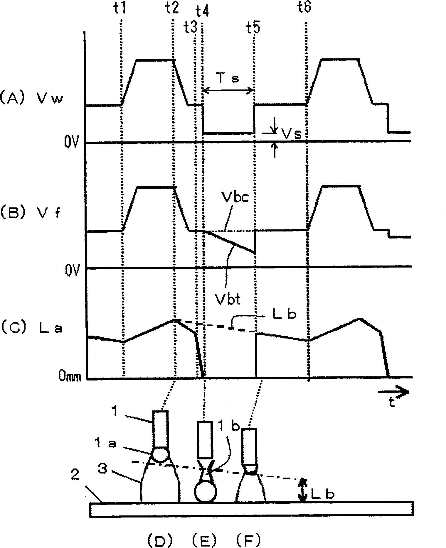
[0035] figure 1 It is a waveform diagram showing the arc length control method of the pulse arc welding according to the first embodiment of the present invention. figure 1 (A) shows the time change of the welding voltage Vw, figure 1 (B) represents the time change of the welding voltage limit value Vf, figure 1 (C) represents the time change of the arc length La, figure 1 (D) to (F) show the state of the arc generating part at each time point. figure 1 with the above Figure 6 Correspondingly, the average arc length is set to be short. exist figure 1 Among them, the operation during the period other than the short-circuit period Ts from time t4 to t5 is the same as the above-mentioned Figure 5 and Figure 6 The same, so the description is omitted. Next, the operation of Ts during the short circuit will be described.

[0036] In Example 1, such as figure 1 As shown in (B), the base voltage lower limit value Vbt gradually decreases with the passage of time in...

Embodiment 2

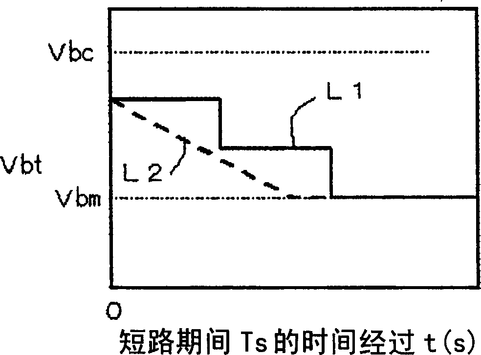
[0042] image 3 It is a graph showing the change pattern of the base voltage lower limit value Vbt with the passage of time during the short-circuit period. image 3 The horizontal axis of represents the elapsed time from the start of the short-circuit period, and the vertical axis represents the value of the base voltage lower limit value Vbt. Such as image 3 As shown, the characteristic L1 drops in steps from the base voltage reference value Vbc. At this time, every few milliseconds, several V drops. In addition, the characteristic L2 falls in a ramp shape, and the maximum lower limit value Vbm is set, and will not fall below this value. The maximum lower limit value Vbm is about 4 to 15V, and an appropriate value is selected according to welding conditions.


PUM


Abstract

In a method for controlling the arc length in pulse arc welding, the mean value of welding voltage Vw composed of peak voltage and base voltage is calculated, and the arc length is kept to be optimum by controlling the pulse period such that the mean value of the welding voltage is approximately equal to the preset value of the voltage. When a short circuit state Ts occurs during a base period and the voltage has changed from the base voltage to the short circuit voltage Vs, the mean value of the welding voltage is calculated by limiting the short circuit voltage Vs to the lower limit Vbt of the base voltage, wherein the lower limit value Vbt of the base voltage is varied so as to be furthermore low with the lapse of time in the short circuit state Ts. In consumable electrode type pulse arc welding the high speed welding, etc. are carried out with a mean arc length set to be short in order to improve the controllability of an arc length.

Description

technical field [0001] The present invention relates to an arc length control method for pulse arc welding that improves arc length controllability by limiting a short-circuit voltage value during a short-circuit period. Background technique [0002] In molten electrode arc welding, in order to obtain good welding quality, it is necessary to maintain the arc length during welding at an appropriate value. In the melting electrode type pulse arc welding in which the energization of the peak current in the peak period and the energization of the base current in the base period are repeatedly energized as one pulse cycle, there has been a method of controlling the arc length by controlling the pulse cycle so that The average value of the welding voltage is approximately equal to the preset voltage setting value, so that the arc length is maintained at an appropriate value. Next, the arc length control method of conventional pulse arc welding will be described. [0003] Figure...

Claims


Application Information

Patent Timeline
Patent Type & Authority Applications(China)
IPC IPC(8): B23K9/09B23K9/073B23K9/095
Inventor 仝红军
Owner DAIHEN CORP
Learn More