Process for producing aromatic polycarbonate
An aromatic carbonate and polycarbonate technology, applied in the field of aromatic polycarbonate manufacturing, can solve the problem of accumulating by-product coloring impurities and coloring impurities
- Summary
- Abstract
- Description
- Claims
- Application Information
AI Technical Summary
Problems solved by technology
Method used
Image

Examples
Embodiment 1
[0217] The present invention will be explained in more detail below with respect to s-PL processing.
[0218] (Manufacture of dehydrated s-PL)
[0219] [PC polymerization step]
[0220] In a nitrogen atmosphere, BPA (manufactured by Mitsubishi Chemical Co., Ltd.; BPA obtained in Reference Example 2 described later) supplied at 34.3 kg / hr (kilogram / hour) and BPA supplied at 33.5 kg / hr were melt-mixed at 130° C. DPC (manufactured by Mitsubishi Chemical Co., Ltd.; DPC obtained in Reference Example 1 described later). The mixture was continuously fed into the first vertical stirring polymerization tank adjusted to normal pressure, nitrogen atmosphere and 210°C through a raw material introduction pipe heated to 130°C. The liquid level was kept constant by adjusting the opening of the valve installed in the polymer discharge line connected to the bottom of the tank, resulting in an average residence time of 60 minutes. In addition, at the same time as the starting of the feed of ...
experiment example 1
[0234] (Experimental Example 1) Production of DPC
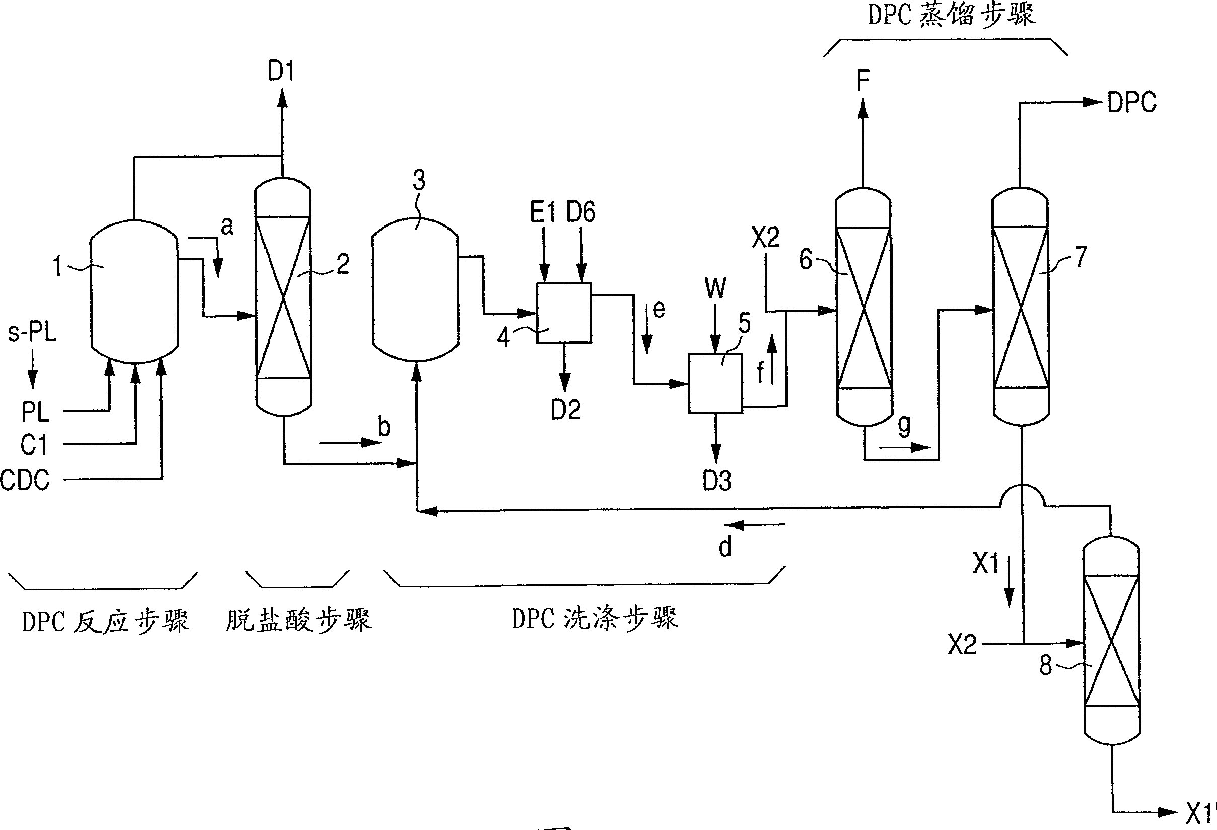
[0235] First, the following methods are explained in detail: Figure 5 The dehydrated s-PL discharged as a distillate from the second PL distillation column shown is used as a raw material for DPC to manufacture DPC, and at the same time, the PC low-boiling distillate ( D6) is recycled to the DPC wash step.
[0236] [DPC reaction step / dehydrochloric acid step]
[0237] according tofigure 1 The flow chart shown carries out the DPC fabrication steps. Incidentally, the DPC reactor 1 used consisted of two reactors connected in series.
[0238] Purified s-PL having a temperature of 50 °C in a molten state was continuously fed at 30.0 kg / hr (0.32 kmol / hr) to the DPC first reactor, while PL containing pyridine was added as a catalyst, the pyridine containing PL is obtained by dehydrating low boiling substances discharged as distillate from a low boiling substance distillation column described later. While thus feeding, the abov...
reference example 1
[0247] (Reference example 1) Manufacture of DPC
[0248] DPC was produced in the same manner as in Experimental Example 1, except that commercially available PL (manufactured by Mitsubishi Chemical Corporation) was used instead of purified s-PL.
[0249] [result]
[0250] It was determined that even when s-PL was used, the same yield as using commercially available PL was obtained and the manufacturing efficiency was maintained.
PUM
| Property | Measurement | Unit |
|---|---|---|
| The inside diameter of | aaaaa | aaaaa |
| The inside diameter of | aaaaa | aaaaa |
| Height | aaaaa | aaaaa |
Abstract
Description
Claims
Application Information
 - R&D
- Intellectual Property
- Life Sciences
- Materials
- Tech Scout
- Unparalleled Data Quality
- Higher Quality Content
- 60% Fewer Hallucinations
Browse by: Latest US Patents, China's latest patents, Technical Efficacy Thesaurus, Application Domain, Technology Topic, Popular Technical Reports.
© 2025 PatSnap. All rights reserved.Legal|Privacy policy|Modern Slavery Act Transparency Statement|Sitemap|About US| Contact US: help@patsnap.com