Method and apparatus for realizing multipath signal re-timing

A multi-channel signal and retiming technology, applied in the field of communication, can solve the problems of high cost and resource waste, and achieve the effects of avoiding waste, improving utilization rate and reducing cost

Active Publication Date: 2006-10-04
DATANG TELECOM TECH CO LTD
View PDF0 Cites 5 Cited by
  • Summary
  • Abstract
  • Description
  • Claims
  • Application Information

AI Technical Summary

Problems solved by technology

[0009] The purpose of the present invention is to provide a method and device for retiming multi-channel signals, so as to solve the technical problems of high cost and serious waste of resources in the prior art

Method used


Image

  • Method and apparatus for realizing multipath signal re-timing
  • Method and apparatus for realizing multipath signal re-timing
  • Method and apparatus for realizing multipath signal re-timing

Examples


Embodiment Construction

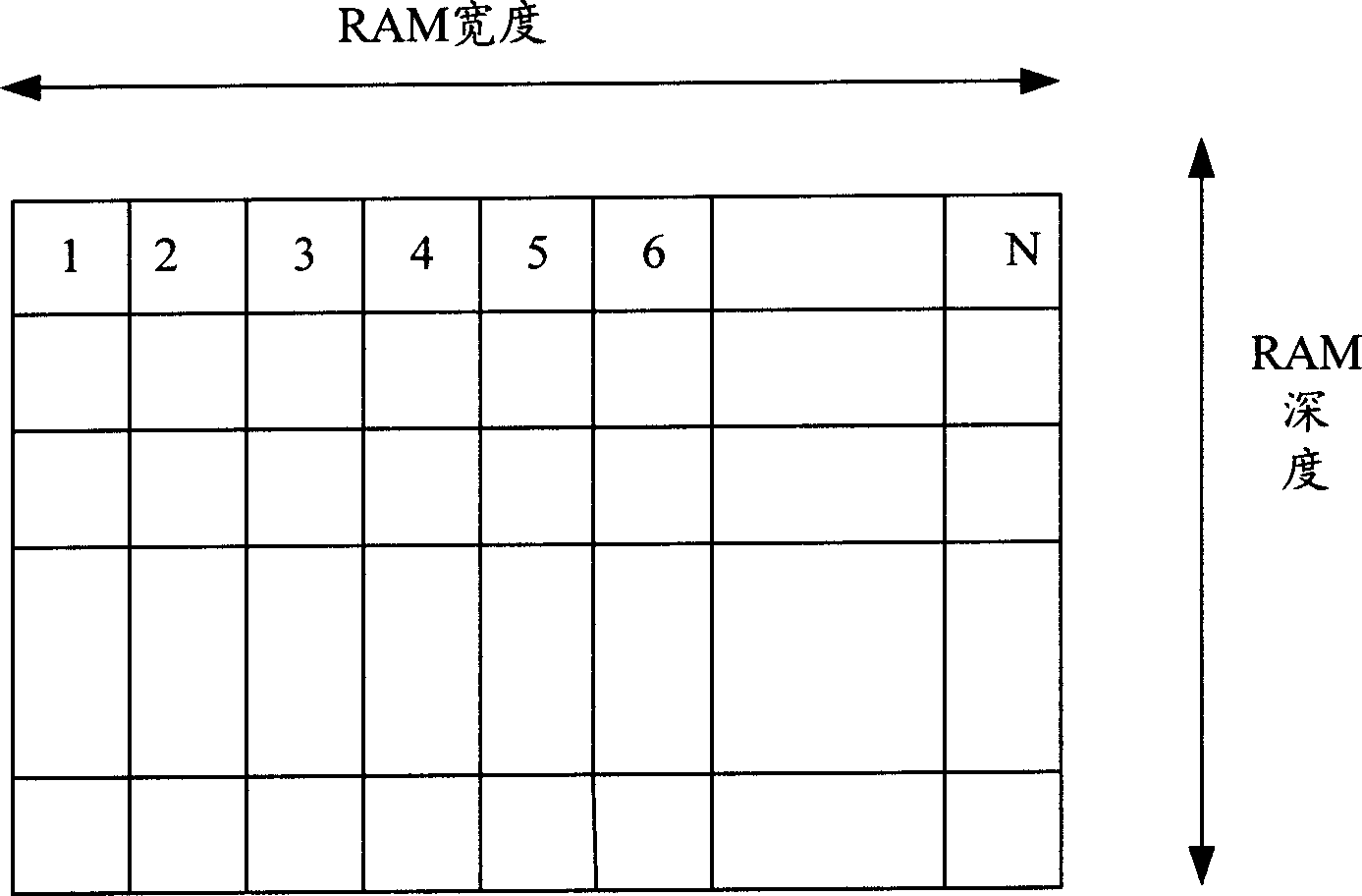
[0040] In the prior art, the method for realizing retiming of multi-channel signals has the technical problems of high cost and serious waste of resources. For this reason, the applicant of the present invention has found through long-term research that the multi-channel signal retiming function can be realized by using the principle of a time-division circuit. Its core lies in: using a high-speed clock source to generate a high frequency (its frequency is higher than M × signal frequency × (number of channels + 1), M is the sum of the number of cycles required for RAM to read data, rewrite data, and write data; signal The clock signal whose frequency is the signal frequency of the low-speed signal that needs to be timed) is used as the system clock, and several time slots are generated by the system clock, and each time slot contains several system clock cycles. The low-speed signal data (one bit) is stored in the RAM respectively, and the data of all channels (one bit for ea...


PUM


Abstract

The invention discloses a method for achieving multi-path signal re-timing, especially to the re-timing of multi-path E1, T1 or other low speed signal. It uses a high speed clock source to generate a high frequency clock signal as system clock; the system clock generates a plurality of time slots; each time slot comprises a plurality of system clock periods; it separately stores the sampled low speed signal data in RAM and reads the data of all the paths of a time slot, which achieves each path synchronic processing.

Description

technical field [0001] The invention relates to the communication field, in particular to a realization method for processing multiple asynchronous signals into multiple synchronous signals. Background technique [0002] SDH system (Synchronous Digital Communication Transmission System) is widely used in important transmission systems such as modern high-speed telecommunication networks and high-speed Internet, and is of great significance to the development of optical fiber, microwave and satellite communication technologies. In the SDH system, data adaptation needs to be adjusted by mapping or pointers. However, during this adjustment process, data jitter and drift will be introduced. In order to avoid and reduce the impact on synchronization timing when this happens, it is necessary to perform Signal timing processing. [0003] see figure 1 , which is a schematic structural diagram of an SDH system. In the local transmission network layer, SDH rings mostly use multiple...

Claims


Application Information

Patent Timeline
Patent Type & Authority Applications(China)
IPC IPC(8): H04J3/16H03M9/00
Inventor 黄浩邓莉
Owner DATANG TELECOM TECH CO LTD
Why Eureka
Try Eureka