Dielectric antenna

A technology for dielectrics and antennas, applied in antennas, resonant antennas, electrical components, etc., can solve problems such as damage and failure to ensure similarity, and achieve an easy-to-form effect

Inactive Publication Date: 2006-10-04
ORMON CORP +1
View PDF4 Cites 2 Cited by
  • Summary
  • Abstract
  • Description
  • Claims
  • Application Information

AI Technical Summary

Problems solved by technology

In this frequency band, if the variation of the VSWR of the antenna is large, the similarity relationship cannot be ensured between the spectrum of the signal input to the antenna and the spectrum of the signal output from the antenna.
As a result, the waveform of the output signal is destroyed from the waveform of the input signal

Method used


Image

  • Dielectric antenna
  • Dielectric antenna
  • Dielectric antenna

Examples


Embodiment 1

[0109] Below, based on the attached Figure 1-18 and Fig. 26 illustrate a first embodiment of the present invention.

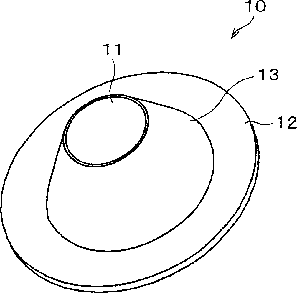
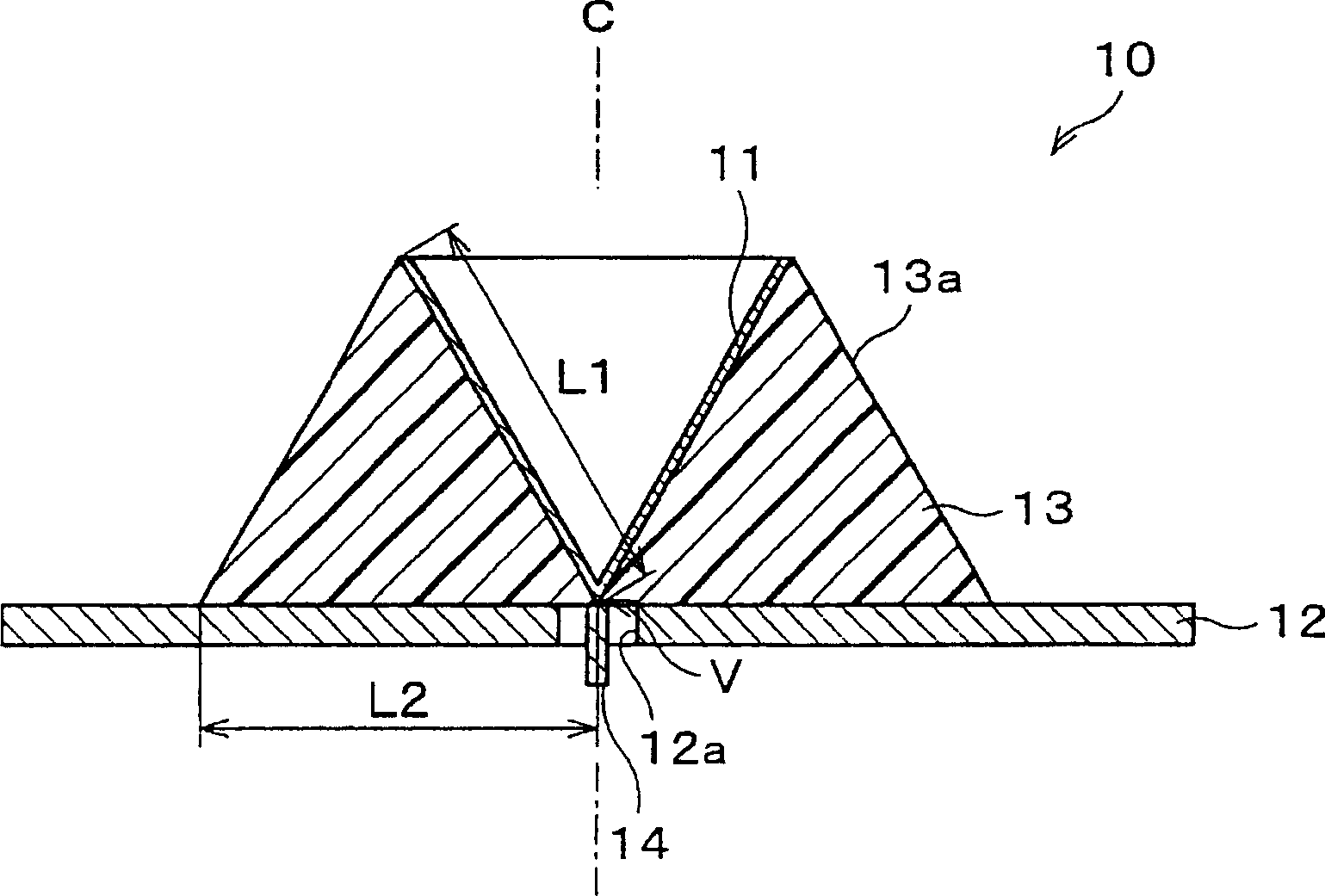
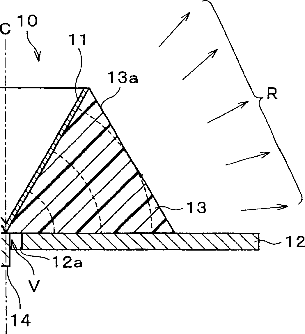
[0110] figure 1 and figure 2 A perspective view and a cross-sectional view of the single conical antenna 10 of this embodiment are respectively shown. The single conical antenna 10 has a power supply electrode 11 , a ground electrode 12 , a dielectric member 13 , and a power supply terminal 14 .

[0111] The power supply electrode 11 is an electrode made of a conductor, and its shape is a tapered surface (conical surface) of a cone. The power supply electrode 11 can be formed by, for example, plating the inner side surface of the dielectric member 13 .

[0112] The ground electrode 12 is an electrode made of a conductor, has a disc shape, and has a concentric cylindrical through-hole 12 a at the center thereof. The ground electrode 12 is perpendicular to the center line of the conical surface formed by the power supply electrode 11, and the center line ...

no. 2 example

[0174] Below, according to Figure 19 ~ Figure 2 6 illustrates the second embodiment of the present invention. In the single conical antennas 30 and 40 described in this embodiment, components having the same functions as those in the single conical antennas 10 and 20 described in the first embodiment are denoted by the same reference numerals, and description thereof will be omitted.

[0175] Figure 19 and Figure 20 A perspective view and a cross-sectional view of the single conical antenna 30 of this embodiment are respectively shown. The single conical antenna 30 has a feeding electrode (first electrode) 11 , a ground electrode (second electrode) 12 , a dielectric member 34 , and a feeding terminal 14 . Here, the power supply electrode 11 , the ground electrode 12 , and the power supply terminal 14 are the same components as those in the first embodiment.

[0176] The dielectric member 34 has the same shape as the dielectric member 13 of Embodiment 1, and is the same ...


PUM


Abstract

A mono-conical antenna as a dielectric antenna includes: a feed electrode having a conical surface; a grounding electrode having a flat surface positioned at the vertex side of the conical surface with respect to the conical surface; and a dielectric member arranged between the conical surface and the flat surface. The outer circumference of the dielectric member has a shape spreading from the conical surface side toward the flat surface side. Thus, the size of the dielectric antenna can be reduced and the dielectric antenna can have a wide range of a frequency band suppressing the maximum value of the VSWR to a small value.

Description

technical field [0001] The present invention relates to an antenna mounted on a dielectric body, in particular to an antenna mounted on a dielectric body suitable for miniaturization and wide frequency band. Background technique [0002] In recent years, the popularity of portable information processing devices having wireless communication functions has been remarkable. As wireless communication of such an information processing device, communication such as a wireless LAN using electromagnetic waves of a frequency in the 2.4 GHz band (2.471 to 2.497 GHz), for example, is often used. [0003] On the other hand, UWB (Ultra Wide Band: Ultra Wide Band) communication using a frequency band much wider than conventional wireless LANs is also proposed. UWB communication is also called pulse communication (impulse radio frequency, impulse radio:), by receiving and sending pulses with a very short width, data is received and sent. In this way, since pulses with a very short width ...

Claims


Application Information

Patent Timeline
Patent Type & Authority Applications(China)
IPC IPC(8): H01Q9/40H01Q13/08H01Q1/38H01Q9/38H01Q19/09
CPCH01Q19/09H01Q9/40
Inventor 桥山真二新开哲夫冈野佑三小林岳彦
Owner ORMON CORP
Why Eureka
Try Eureka