Static dust collection system

A technology of electrostatic precipitator and electrostatic precipitator, which is applied in the field of electrostatic precipitator system, can solve the problems of energy waste, electric field distortion, and excessive emission, and achieve the effects of reducing energy consumption, improving automation level, and reducing energy consumption

Inactive Publication Date: 2006-10-11
WUYI UNIV
View PDF1 Cites 24 Cited by
  • Summary
  • Abstract
  • Description
  • Claims
  • Application Information

AI Technical Summary

Benefits of technology

This technology helps prevent damage caused by excessive accumulation on power cables used for electric discharge cleaning (EDC). By measuring these factors like air pressure or moisture levels with sensors installed inside an ECD machine, this allows for precise adjustment over different operating conditions such as voltage, current flow rate, etc., which improves overall performance and lifespan of the device's components. Additionally, there may be connections across multiple networks connecting both devices within the same organization. Overall, this technology simplifies the way we operate electrical dischargers while reducing their impact on our environment.

Problems solved by technology

This patented technical solution described by me describes how electrical fields can help reduce harmful particulate matter (PM) levels during combustion processes such as coal burning plants that produce large amounts of exhaust gases containing fine suspended solids called fly ash. Current solutions involve removing PM through filters made up mostly of traditional materials like metal wire mesh screens. These filtering systems have limitations in terms of their ability to effectively filter small solid particles while also being able to handle larger quantities of mist without increasing pressure drop overcomes issues associated with current technologies involving lined plasma generators.

Method used


Image

  • Static dust collection system
  • Static dust collection system
  • Static dust collection system

Examples


Embodiment Construction

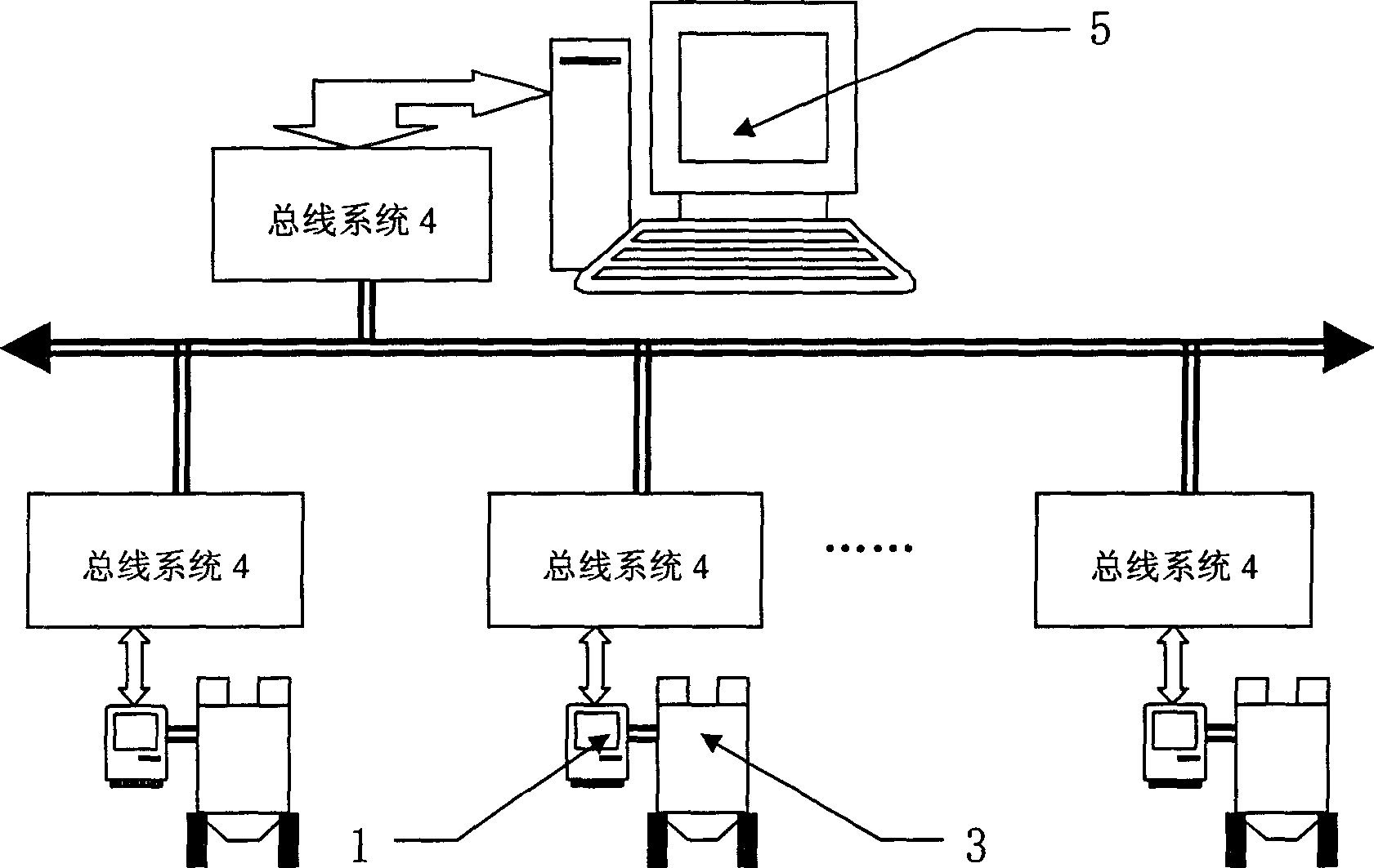
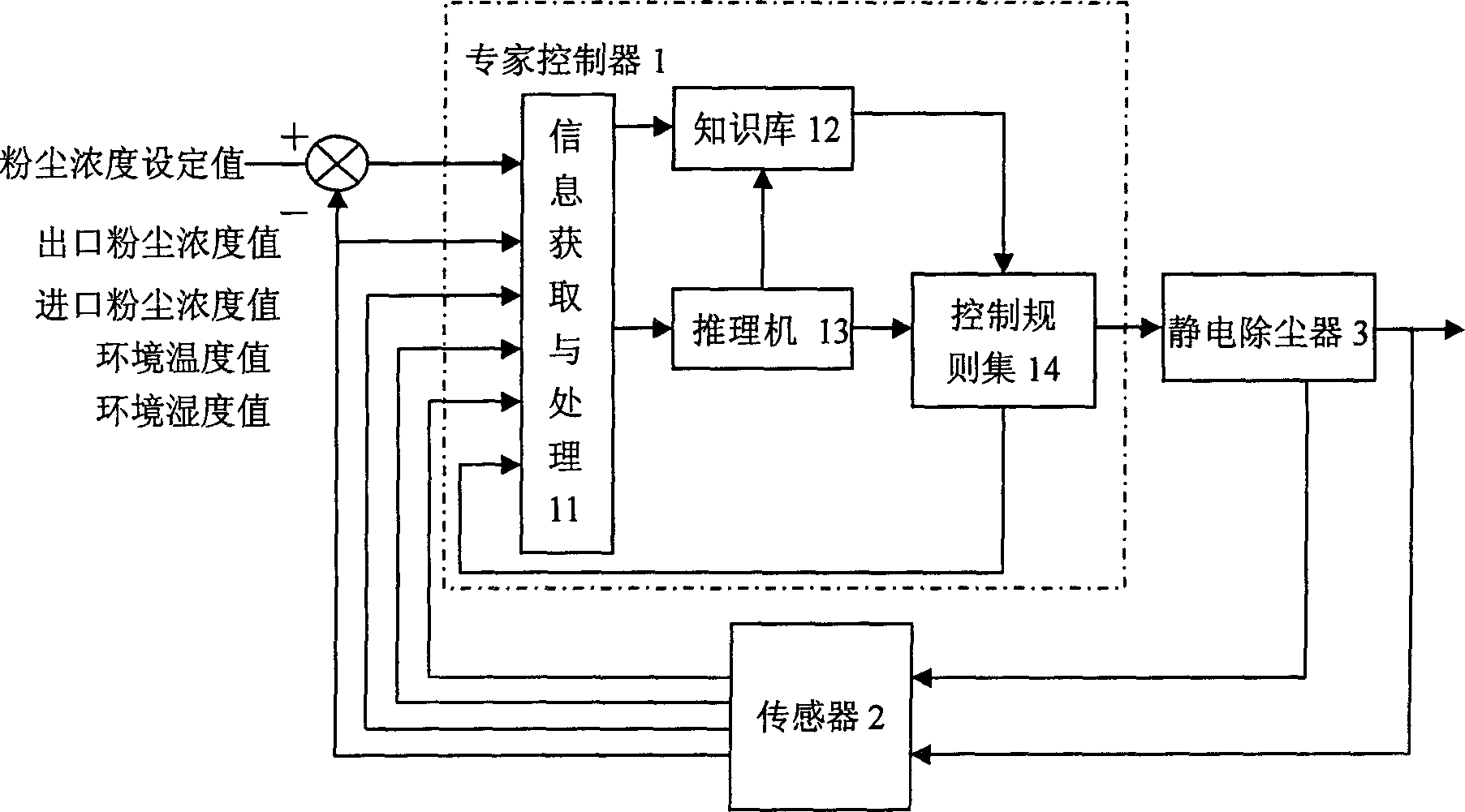
[0015] refer to figure 1 , an electrostatic precipitator system, including an electrostatic precipitator 3, an expert controller 1 and a sensor 2 arranged in the electrostatic precipitator 3, the output of the sensor 2 is connected to the input end of the expert controller 2, and the output end of the expert controller 1 is connected to the electrostatic precipitator The electric field voltage control circuit of 3 is connected; the sensor 2 detects the corresponding data in the electrostatic precipitator 3 and sends it to the expert controller 1 for analysis and processing, and generates a control signal to control the electric field voltage control circuit of the electrostatic precipitator 3, and then adjusts the electrostatic precipitator The dust removal intensity of 3 keeps the dust concentration at the outlet stable at the set value.

[0016] The structure, working principle and process of the electrostatic precipitator system are described in detail below.

[0017] The ...


PUM


Abstract

The invention relates to a static dedusting device, which comprises: a static deduster, a expert controller, and a sensor inside the static deduster. Wherein, the outlet of sensor is connected to the inlet of expert controller; the outlet of expert controller is connected to the electric field voltage control circuit of static deduster; the sensor detects the data of static deduster to be transmitted to the expert controller to be analyzed and treated and generate a control signal to control the electric filed voltage control circuit, and adjust the dedusting force to stabilize the powder density of outlet at preset valve. The invention can solve the problems that the change of powder density at the inlet is lag to discharged powder density; while it can reduce energy consumption with qualified powder density at outlet. Via bus system, the network control system can be built to realize remote detection on each note, modifying note expert controller and the control parameters of static deduster.

Description


Claims


Application Information

Patent Timeline
Owner WUYI UNIV
Why Eureka
Try Eureka