Selective catalytic reduction denitration method for flue gas

A catalytic denitrification and selective technology, applied in chemical instruments and methods, separation methods, gas treatment, etc., can solve problems such as high carbon monoxide concentration and pollution, and achieve the effects of controlling emissions, wide application range, and reducing emissions

Inactive Publication Date: 2019-01-22
TSINGHUA UNIV
View PDF6 Cites 7 Cited by
  • Summary
  • Abstract
  • Description
  • Claims
  • Application Information

AI Technical Summary

Problems solved by technology

The low-nitrogen combustion technology in the furnace can significantly reduce the original emission of nitrogen oxides, which is very positive for the overall reduction of the final emission of nitrogen oxides. The concentration of carbon monoxide in the exhaust gas is relatively high, and if it is not properly controlled, it will cause new pollution problems

Method used


Image

  • Selective catalytic reduction denitration method for flue gas

Examples


Embodiment 1

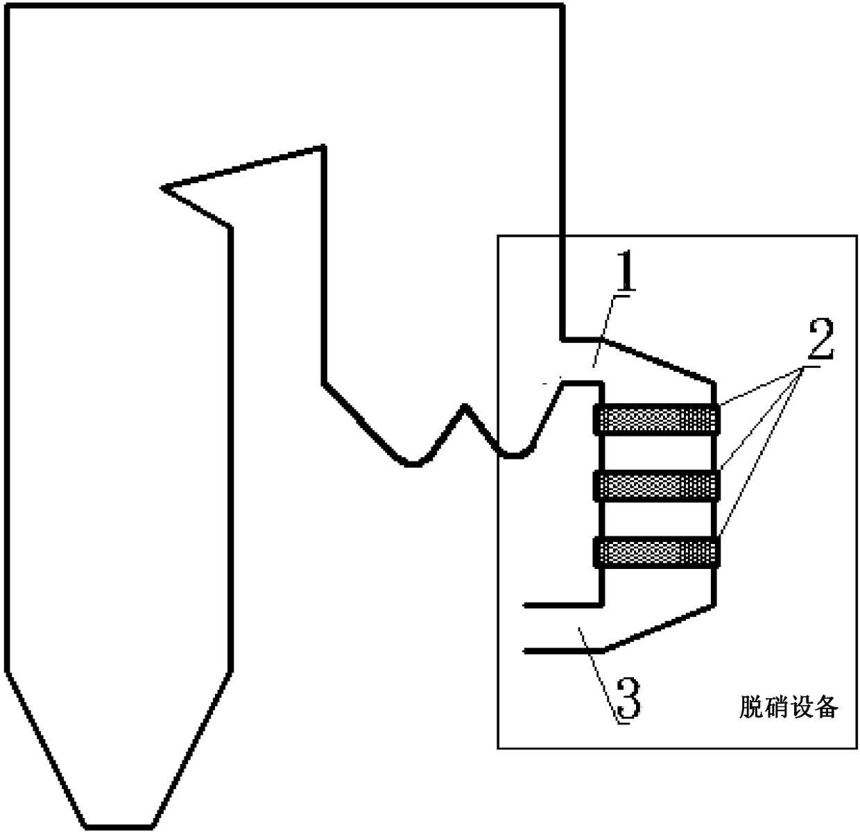
[0030] There are three layers of Al in the denitrification equipment 2 o 3 As the base carrier, mainly MnO, Fe 2 o 3 , CeO 2A honeycomb catalyst in which a mixture of metal oxides is an active ingredient. The flow velocity of the hot flue gas is 7m / s, the temperature of the flue gas at the reactor inlet is 385°C, and the temperature at the reactor outlet is 300°C. The carbon monoxide concentration in the initial flue gas is 544mg / Nm 3 , the concentration of nitrogen oxides is 105mg / Nm 3 . The concentration of carbon monoxide in the flue gas after catalytic treatment is 432mg / Nm 3 , the concentration of nitrogen oxides is 26mg / Nm 3 .

Embodiment 2

[0032] In the embodiment of the present invention, the catalyst in the denitrification equipment is the same as that in embodiment 1.

[0033] The flow rate of the hot flue gas is 3m / s, the temperature of the flue gas at the reactor inlet is 380°C, and the temperature at the reactor outlet is 260°C. The carbon monoxide concentration in the initial flue gas is 314mg / Nm 3 , the concentration of nitrogen oxides is 176mg / Nm 3 . The concentration of carbon monoxide in the flue gas after catalytic treatment is 103mg / Nm 3 , the concentration of nitrogen oxides is 41mg / Nm 3 .

Embodiment 3

[0035] In the embodiment of the present invention, the catalyst in the denitrification equipment is the same as that in embodiment 1.

[0036] The flow rate of the hot flue gas is 5m / s, the temperature of the flue gas at the reactor inlet is 388°C, and the temperature at the reactor outlet is 297°C. The carbon monoxide concentration in the initial flue gas is 446mg / Nm 3 , the concentration of nitrogen oxides is 131mg / Nm 3 . The concentration of carbon monoxide in the flue gas after catalytic treatment is 265mg / Nm 3 , the concentration of nitrogen oxides is 40mg / Nm 3 .


PUM


Abstract

The invention provides a selective catalytic reduction denitration method for flue gas, wherein the method comprises the following technological steps: feeding flue gas to be treated into a selectivecatalytic denitration device; taking carbon monoxide in the flue gas as a reductant, and under the action of a catalyst, carrying out redox reaction with nitrogen oxides in the flue gas; reducing thenitrogen oxides in the flue gas into nitrogen gas, and oxidizing carbon monoxide into carbon dioxide, and outputting carbon dioxide from an outlet of the denitration device. According to the selectivecatalytic reduction denitration method of the flue gas, carbon monoxide contained in the flue gas itself is used as the reductant, and undergoes reaction with the nitrogen oxides in the flue gas under the action of the catalyst, and the emission of carbon monoxide is significantly reduced while the nitrogen oxides are reduced. Not only does the problem of ammonia escape not exist, but also the problems of secondary pollution and downstream corrosion caused by ammonia escape can be solved.

Description

technical field [0001] The invention relates to the technical field of thermal energy engineering, in particular to a method for selective catalytic reduction and denitrification of flue gas. Background technique [0002] Nitrogen oxides are one of the most important air pollutants. Historically, the excessive emission of nitrogen oxides has caused public hazards such as the photochemical smog in Los Angeles in 1943 and the photochemical smog in Tokyo in 1971. Nitrogen oxides mainly come from flue gas after fuel combustion. In response to this problem, most power plant boilers use selective catalytic reduction (SCR) denitrification technology to reduce nitrogen oxide emissions. The current typical SCR denitrification technology for coal-fired power plant boilers is to directly spray the reducing agent ammonia or urea into the flue, and in the reactor, the surface of the catalyst selectively reacts with the nitrogen oxides in the flue gas to reduce the nitrogen oxides. into...

Claims


Application Information

Patent Timeline
Patent Type & Authority Applications(China)
IPC IPC(8): B01D53/86B01D53/56
CPCB01D53/8625B01D2251/204B01D2255/106B01D2258/0283
Inventor 张扬张海岳光溪
Owner TSINGHUA UNIV
Why Eureka
Try Eureka