Brick-unloading machine

A brick unloading machine and rack technology, applied in the direction of unloading devices, manufacturing tools, etc., can solve the problems of unfavorable mechanized production, low efficiency, high labor intensity, etc., to reduce floor space, reduce labor intensity, and improve production efficiency effect

Inactive Publication Date: 2006-10-11
FUJIAN HAIYUAN AUTOMATIC EQUIP CO LTD
View PDF0 Cites 3 Cited by
  • Summary
  • Abstract
  • Description
  • Claims
  • Application Information

AI Technical Summary

Problems solved by technology

[0002] In the brick production process of the prior art, after the bricks are formed, the bricks need to be stacked on the maintenance trolley for maintenance. The bricks stacked on the maintenance trolley are as follows: figure 1 As shown, in this way, after maintenance, the bricks need to be transported from the maintenance trolley to be stacked, but at present, the bricks are transported manually, which is labor-intensive and inefficient, which is not conducive to mechanized production

Method used


Image

  • Brick-unloading machine
  • Brick-unloading machine
  • Brick-unloading machine

Examples


Embodiment Construction

[0047] Best practice:

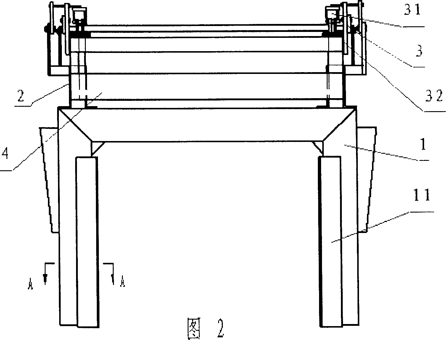
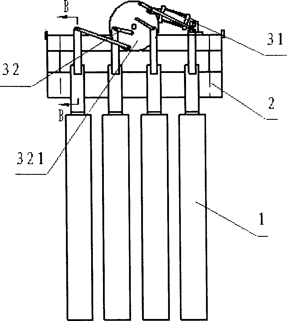
[0048] Referring to Figure 2, image 3 , Figure 4 , Figure 5 , Figure 8, a brick unloading machine, comprising a linear guide rail 2, a closing device 3, a frame 4 and a plurality of manipulators 1, the manipulator 1 has a clamping mechanism 11, each manipulator 1 is distributed on the linear guide rail 2 in parallel, and is connected with the closing device 3, The linear guide rail 2 is fixed on the frame 4. The manipulator 1 is an inverted U-shaped frame, and the clamping mechanism 11 is symmetrically distributed on the two feet of the U-shaped frame. The U-shaped bottom of the U-shaped frame is connected with the linear guide rail 2, and has two linear guide rails 2, and the two linear guide rails 2 are distributed in parallel. on both sides of the U-shaped frame. Each manipulator 1 has a clamping mechanism, and the clamping mechanism 11 is symmetrically distributed on the two legs of the U-shaped frame. Closing device 3 comprises first powe...


PUM


Abstract

The invention relates to a device for discharging final product, especially providing a brick discharger, which comprises a straight guide rail, a folder, a frame and dual mechanical hands. Wherein, said mechanical hands are mounted with clampers; all mechanical hands are parallel arranged on the straight guide rail to connect the folder; said straight guide rail is fixed on the frame. With said invention, it can realize mechanical operation, and avoid the distance between bricks to reach more bricks in unit volume. And it can reduce the labor force, improve producing efficiency and reduce occupied area.

Description

technical field [0001] The invention relates to a device for discharging shaped products from the device, in particular to a brick unloading machine. Background technique [0002] In the brick production process of the prior art, after the bricks are formed, the bricks need to be stacked on the maintenance trolley for maintenance. The bricks stacked on the maintenance trolley are as follows: figure 1 As shown, in this way, after maintenance, the bricks need to be transported from the maintenance trolley to be stacked, but at present, the bricks are transported manually, which is labor-intensive and inefficient, which is unfavorable for mechanized production. Contents of the invention [0003] The purpose of the present invention is to overcome the deficiencies in the prior art and provide a brick unloading machine capable of reducing labor intensity and improving production efficiency. [0004] The object of the present invention is achieved through the following approach...

Claims


Application Information

Patent Timeline
Patent Type & Authority Applications(China)
IPC IPC(8): B28B13/04
Inventor 李良光
Owner FUJIAN HAIYUAN AUTOMATIC EQUIP CO LTD
Why Eureka
Try Eureka