Oil scraper ring ring groove arrangement for pistons of internal combustion engines

A technology for oil scraping rings and internal combustion engines, which is applied to piston rings, mechanical equipment, engine components, etc., can solve problems such as engine wear, and achieve the effects of reducing production costs, reducing axial height, and increasing tangential force.

Active Publication Date: 2006-10-11
MAHLE GMBH
View PDF2 Cites 0 Cited by
  • Summary
  • Abstract
  • Description
  • Claims
  • Application Information

AI Technical Summary

Problems solved by technology

However, this creates a high surface pressure on the working face of the steel disc, resulting in high wear when the engine is running

Method used


Image

  • Oil scraper ring ring groove arrangement for pistons of internal combustion engines
  • Oil scraper ring ring groove arrangement for pistons of internal combustion engines
  • Oil scraper ring ring groove arrangement for pistons of internal combustion engines

Examples


Embodiment Construction

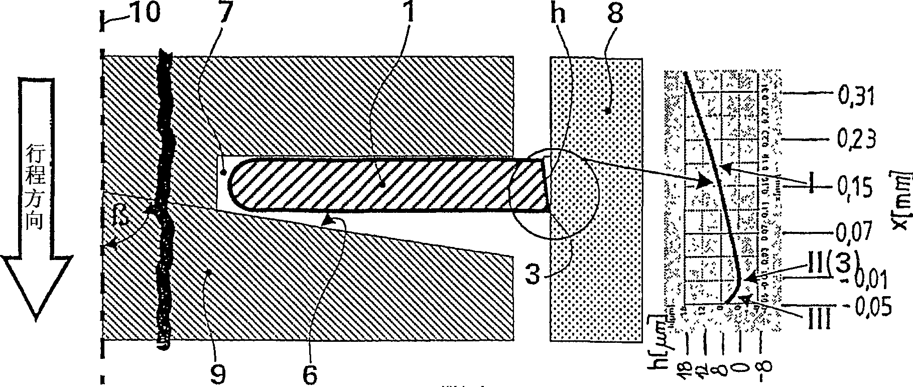
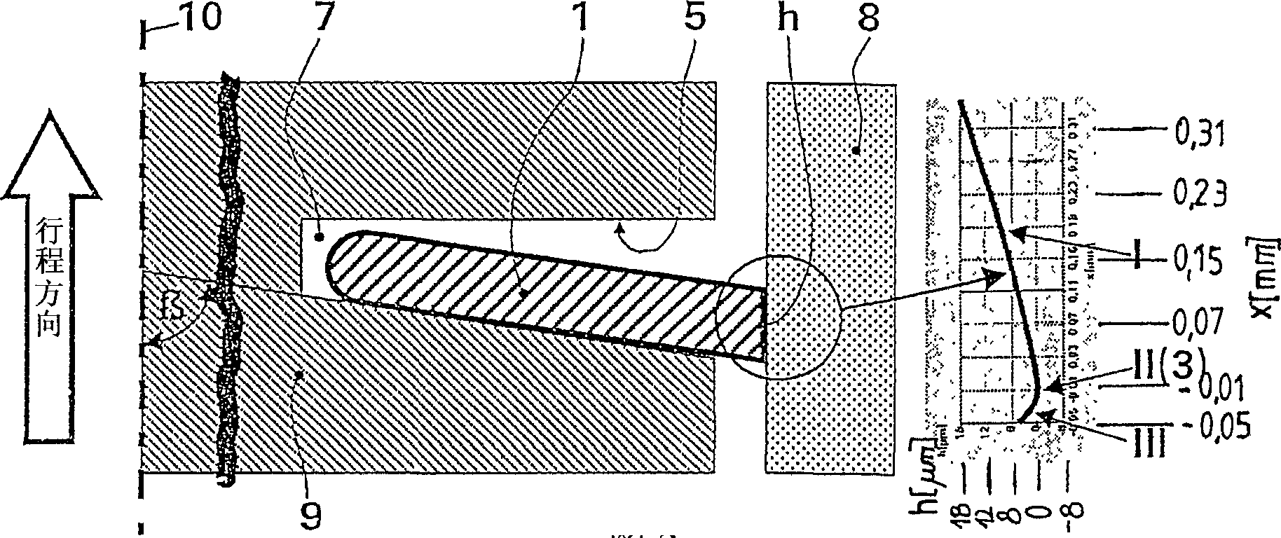
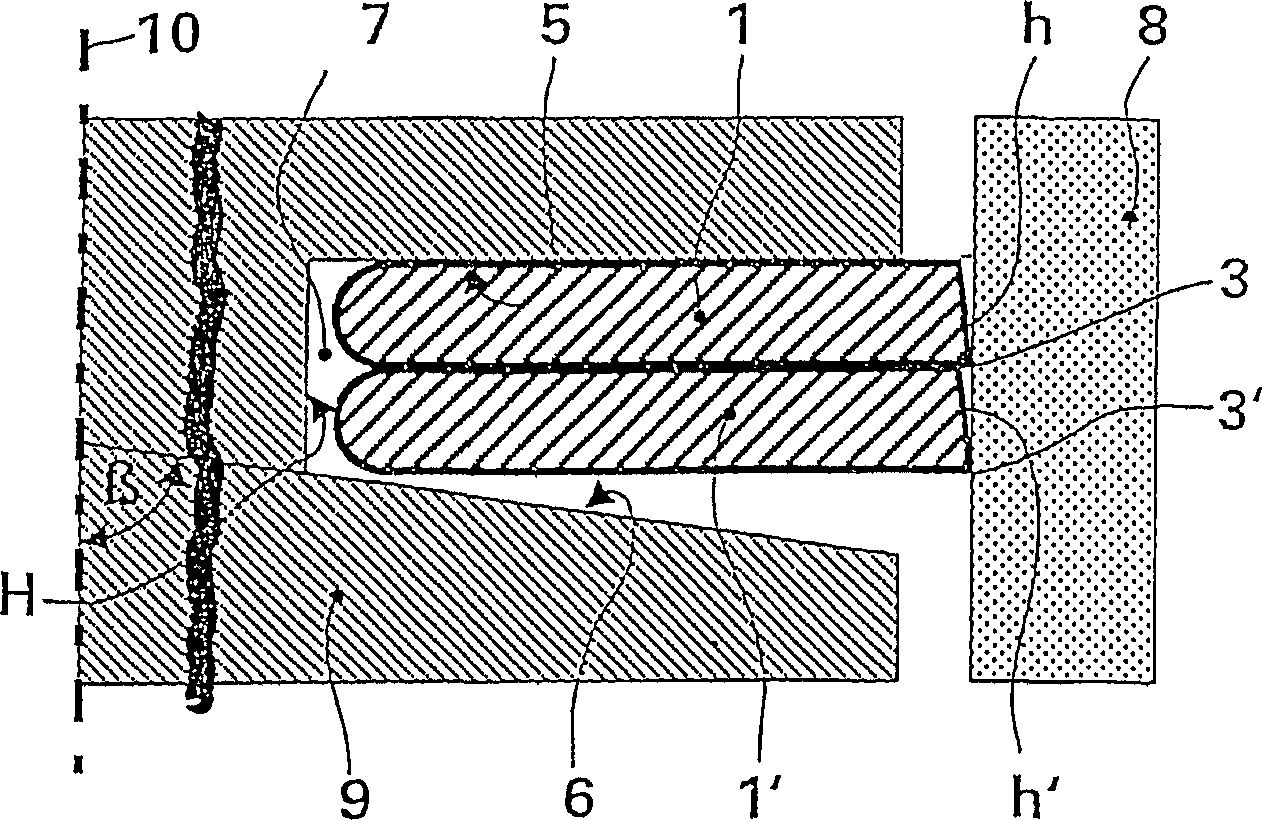
[0032] from figure 1 and figure 2 It can be seen that an oil scraper ring groove arrangement is formed by a disk 1 with a parallel side and a running surface h. The disc 1 is arranged in an annular groove 7 of a piston 9 with its running face h aligned to the cylinder wall 8 of the engine. One ring groove side 5 represents the side of the top side of the piston, and one ring groove side 6 represents the side facing away from the piston top. According to the invention, the ring groove side 5 on the piston top side is aligned at 90° to the piston shaft 10 , wherein the ring groove side 6 facing away from the piston top extends at an angle β in the range of 85° to 87° to the outer diameter of the piston.

[0033] According to the arrangement of the oil wiper ring groove, the disk 1 has a coronal asymmetrically shaped working surface h, which contains a vertex line 3 extending around the periphery of the disk, wherein the vertex line 3 acts as the oil scraper ring and The edge...


PUM


Abstract

The invention relates to an oil scraper ring groove ring arrangement for pistons of internal combustion engines. The inventive arrangement comprises a disk that is provided with parallel flanks and a bearing surface having an asymmetrical crowned form with a vertex line extended over the periphery of the disc, with the disk being arranged in a ring groove of the piston with a ring groove side opposing the piston head and a ring groove side facing the piston head. The aim of the invention is to achieve an improved oil scraping action compared to that of prior art, while reducing the friction and the abrasion in such a way that it is radially outwardly inclined to the outer diameter of the piston, the bearing surface of the disk being embodied in such a way that it corresponds to an almost worn end contour in the started engine state, and, when the oil scraper ring is mounted in the piston, the vertex line of the bearing surface is oriented in the direction of the ring groove side opposing the piston head.

Description

technical field [0001] The invention relates to an arrangement of oil wiper ring grooves for pistons of internal combustion engines, the arrangement comprising a disk with parallel sides, the running surface of which has a crown-shaped asymmetrical shape comprising a strip in the circle The apex line extending on the periphery of the disk, wherein the disk is arranged in a ring groove of the piston, which ring groove has a ring groove side facing away from the top side of the piston and facing the top side of the piston. Background technique [0002] Excessive engine oil reaching the combustion chamber, in addition to high fuel consumption, can also negatively affect the engine's emissions performance. In order to prevent this phenomenon, a sufficient tangential force of the oil wiper ring to generate a radial contact pressure on the cylinder wall, and thus a good oil scraping action, is indispensable. However, this creates a high surface pressure on the working face of the...

Claims


Application Information

Patent Timeline
Patent Type & Authority Applications(China)
IPC IPC(8): F16J9/20
CPCF16J9/203F02F5/00F16J9/00F16J9/20
Inventor 罗尔夫-格哈德·菲德勒
Owner MAHLE GMBH
Why Eureka
Try Eureka