
Microwave themal compression machine bench

A thermal compressor, microwave technology, used in punching machines, presses, furnace types, etc., can solve problems such as deformation, moisture content deviation, etc.

Inactive Publication Date: 2006-10-18
孙辰豪
View PDF0 Cites 4 Cited by
  • Summary
  • Abstract
  • Description
  • Claims
  • Application Information

AI Technical Summary

Problems solved by technology

There are other microwave dryers on the market. At present, tunnel-type or small-scale drying room models are mainly used. Although many problems existing in high-frequency dryers can be improved, due to the deviation of moisture content in different parts of thick materials, the initial drying After drying, it needs to be placed for a period of time to achieve uniform moisture, and then go through the second or third drying process to complete the drying process. In addition, thin materials may have the worry of deformation caused by high-speed drying.
[0007] It can be seen that there are still many deficiencies in this commonly used item, and it is not a good designer, and needs to be improved urgently

Method used


Image

  • Microwave themal compression machine bench
  • Microwave themal compression machine bench
  • Microwave themal compression machine bench

Examples


Embodiment 1

[0059] The microwave thermal compressor table is described in detail below according to an implementation case of the present invention:

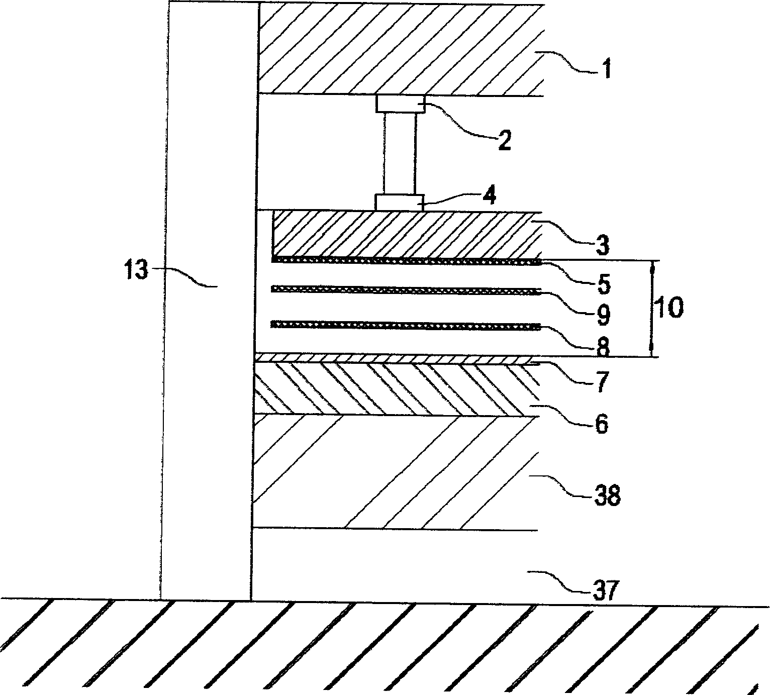
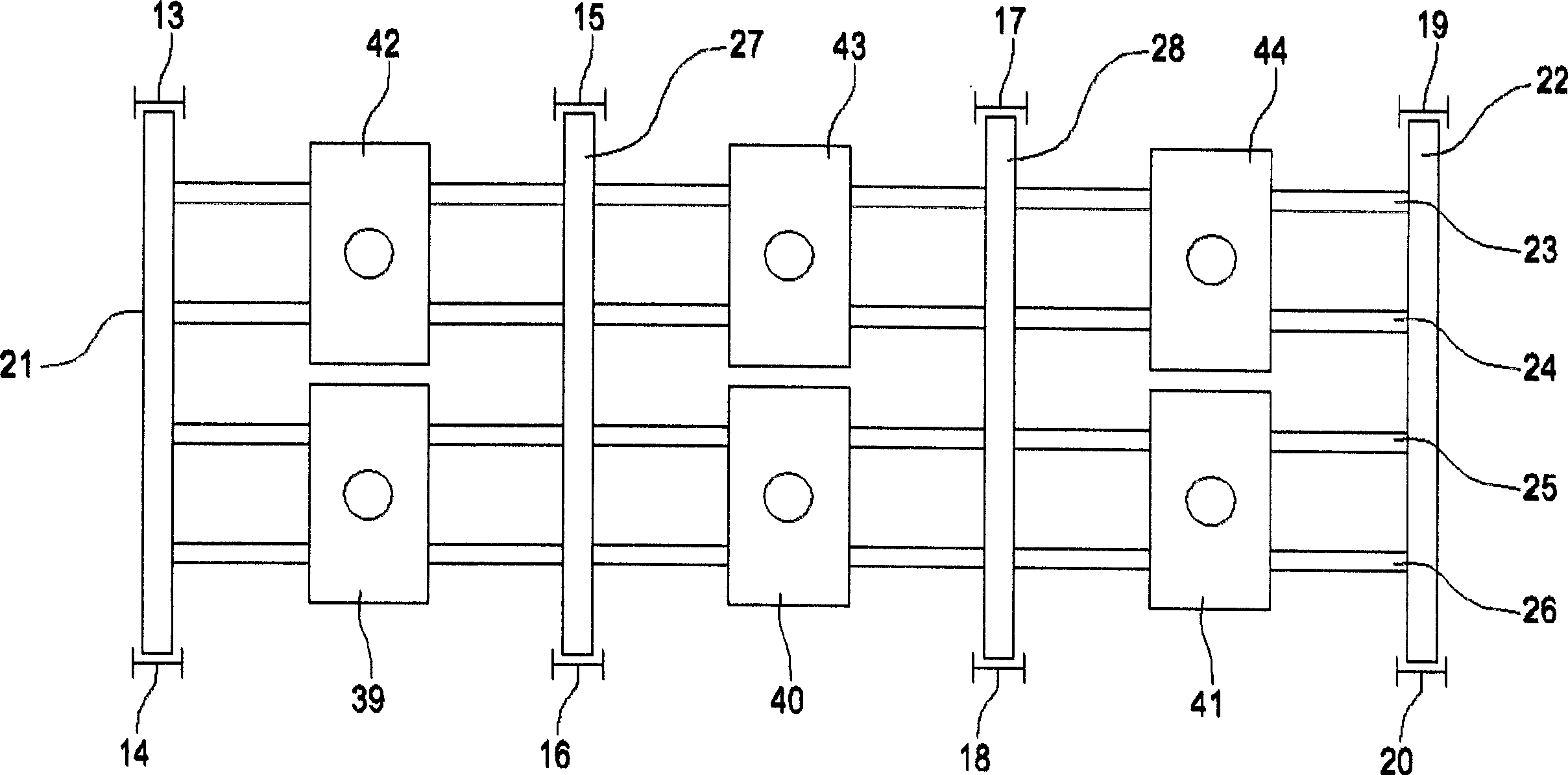
[0060] For the convenience of description, the description of the implementation of the present invention focuses on the fixed lower plate, and the upper plate moves up and down to expand and compress. It has a structure of multi-layer laminated plates, and the pressed object enters and exits from the longitudinal side, and the irradiation part is arranged inside the lower plate. A typical microwave thermal compressor table.

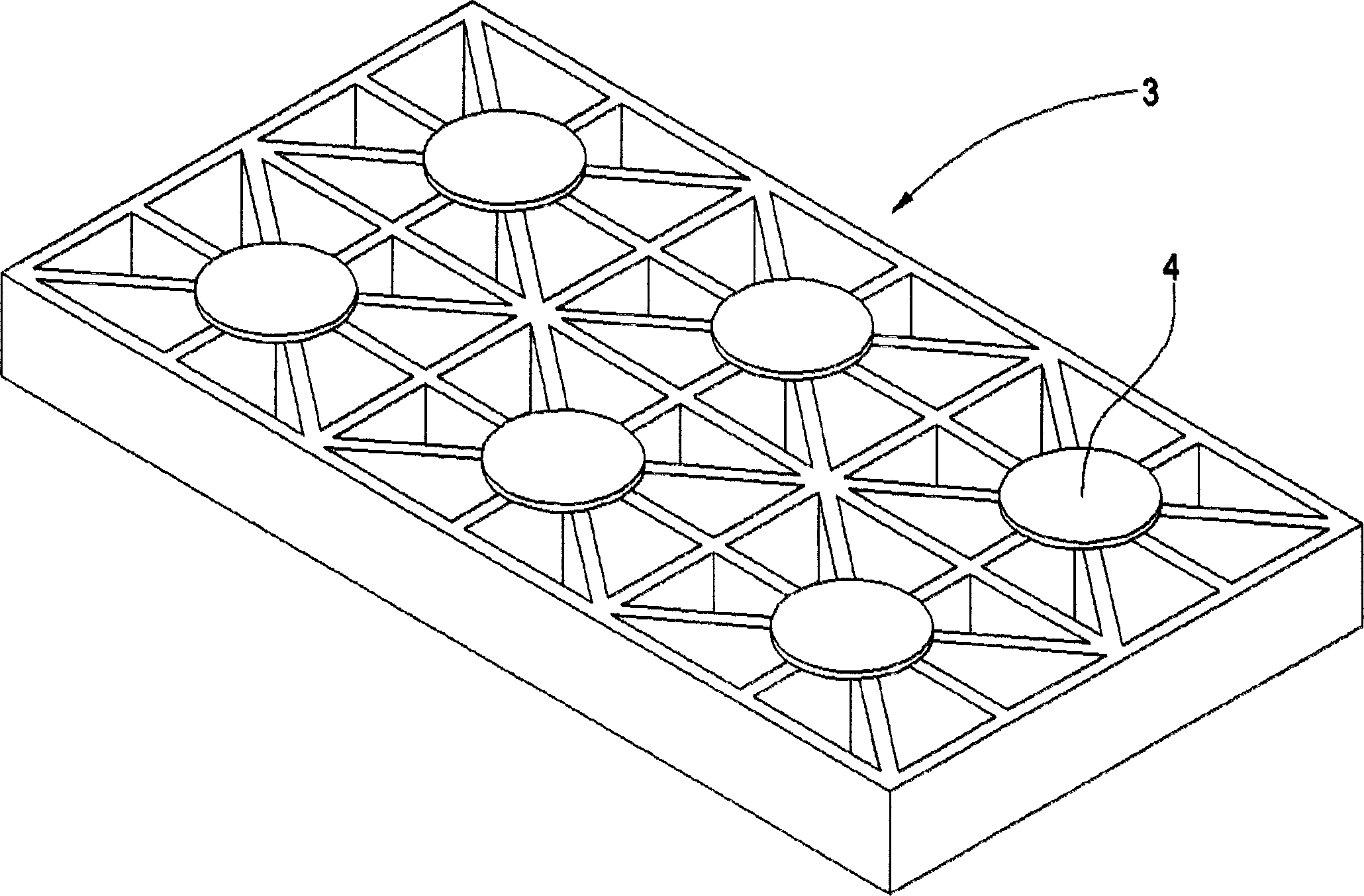
[0061] see Figure 1 to Figure 6 , the compression driving part is composed of six 154.5 metric-ton hydraulic cylinders with a cylinder diameter of 250mm, a plug rod diameter of 180mm, a stroke distance of 360mm, and a pressure of 31.5MPa, which are arranged at the lower end of the upper part 1 of the outer frame. , with a thickness of 30mm marked as a square steel plate 2, and the figure 1 and image 3 Between the...


PUM


Abstract

A hot compressing equipment using a microwave is provided to heat, dry and compress form the compressing object by irradiating a microwave generated from a microwave generator onto a compressing plate to heat the compressing plate, placing a compressing object between the compressing plate and a metallic reflection plate, and compressing the compressing object by the heated compressing plate. In a compressor for applying a pressure to an object placed in a compression chamber to compress the object, a hot compressing equipment using a microwave comprises an irradiation part installed at one side of the compression chamber to irradiate a microwave with a frequency of 300 to 300,000 MHz into the compression chamber such that the microwave heats the object in the compression chamber. The compression chamber has a metallic reflection plate(5) attached to at lest one of inner side faces thereof to reflect the microwave, and at least one compressing plate(8,9) installed on the inner side faces or an inner part thereof in a planar or curved plate-shape to pass through the microwave.

Description

technical field [0001] The invention relates to a microwave thermal compressor table, in particular to a pressing plate formed by irradiating microwaves generated by a microwave generating device on a material that allows microwaves to penetrate, and placing objects to be pressurized into the pressing plate and the Between the metal reflectors, the reflected and penetrated microwaves are used to make the internal molecules of the pressed object oscillate and rub to generate heat and the heat of the medium reaction heated pressing plate and reflecting plate, to heat and dry the pressed object at the same time, through the pressing plate and reflecting plate Microwave thermal compressor table for heating, forming, drying or pressing objects to be pressed. Background technique [0002] It is known to use the pressing plate to pressurize the pressed object loaded between the pressing plates, and the pressurizing device for pressing the pressed object to form or press the skin an...

Claims


Application Information

Patent Timeline
IPC IPC(8): B30B1/32B30B15/34
CPCB21J1/06B21J17/00B30B15/34
Inventor 孙辰豪
Owner 孙辰豪
Learn More