External color filter and the color LCD panel structure therewith

A color filter and liquid crystal display technology, applied in static indicators, instruments, optics, etc., can solve the problems of affecting the curing effect of the PI layer, increasing process requirements, and increasing production costs, so as to improve the uniformity of box thickness and reduce The effect of material loss and cost saving

Inactive Publication Date: 2006-10-18
深圳市合力泰光电有限公司
View PDF0 Cites 12 Cited by
  • Summary
  • Abstract
  • Description
  • Claims
  • Application Information

AI Technical Summary

Problems solved by technology

Therefore, this structure has the following defects. First, there are two problems in sputtering the ITO layer on the color film: one is that it needs to be under low temperature conditions, and the other is to prevent the color film from being damaged during the sputtering process.
In addition, when the PI layer is cured, in order to prevent damage to the color film, the curing temperature needs to be lowered, thereby affecting the curing effect of the PI layer, which greatly increases the process requirements for the production of color liquid crystal display boxes.
Secondly, the existence of the color film will also have a negative impact on the uniformity of the cell thickness, which is very unfavorable for STN-LCDs that have high requirements on the uniformity of the cell thickness.
Third, when a defective color filter film is found or produced during the liquid crystal display box forming process, the detection of the defective color filter film will also affect other components (such as liquid crystal display box, IC, FPC, etc.), these Greatly increased unnecessary material loss, thereby increasing production costs

Method used


Image

  • External color filter and the color LCD panel structure therewith
  • External color filter and the color LCD panel structure therewith
  • External color filter and the color LCD panel structure therewith

Examples


Embodiment 1

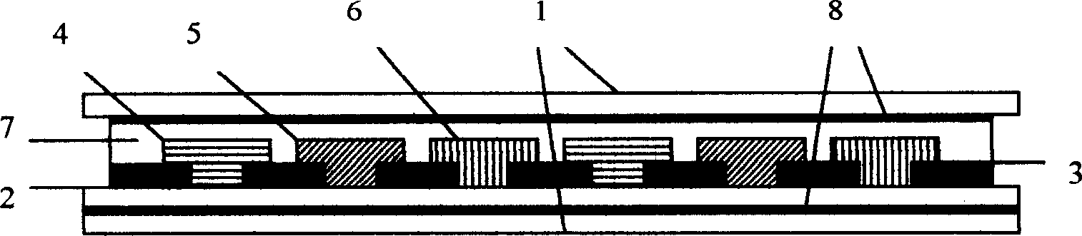
[0026] see image 3 , which is a schematic structural diagram of the external color filter according to the first embodiment of the invention. It includes a substrate 2 made of a transparent polymer flexible material (the substrate can also be made of glass), firstly a black matrix pattern 3 made on the substrate 2, and then step by step to make red 4, green 5, blue 6 Tri-color tinting layer. And an OC layer 7 is made on the colored layer, wherein a protective layer 1 is respectively bonded to the upper surface of the OC layer 7 and the lower surface of the substrate 2 through an adhesive 8 .

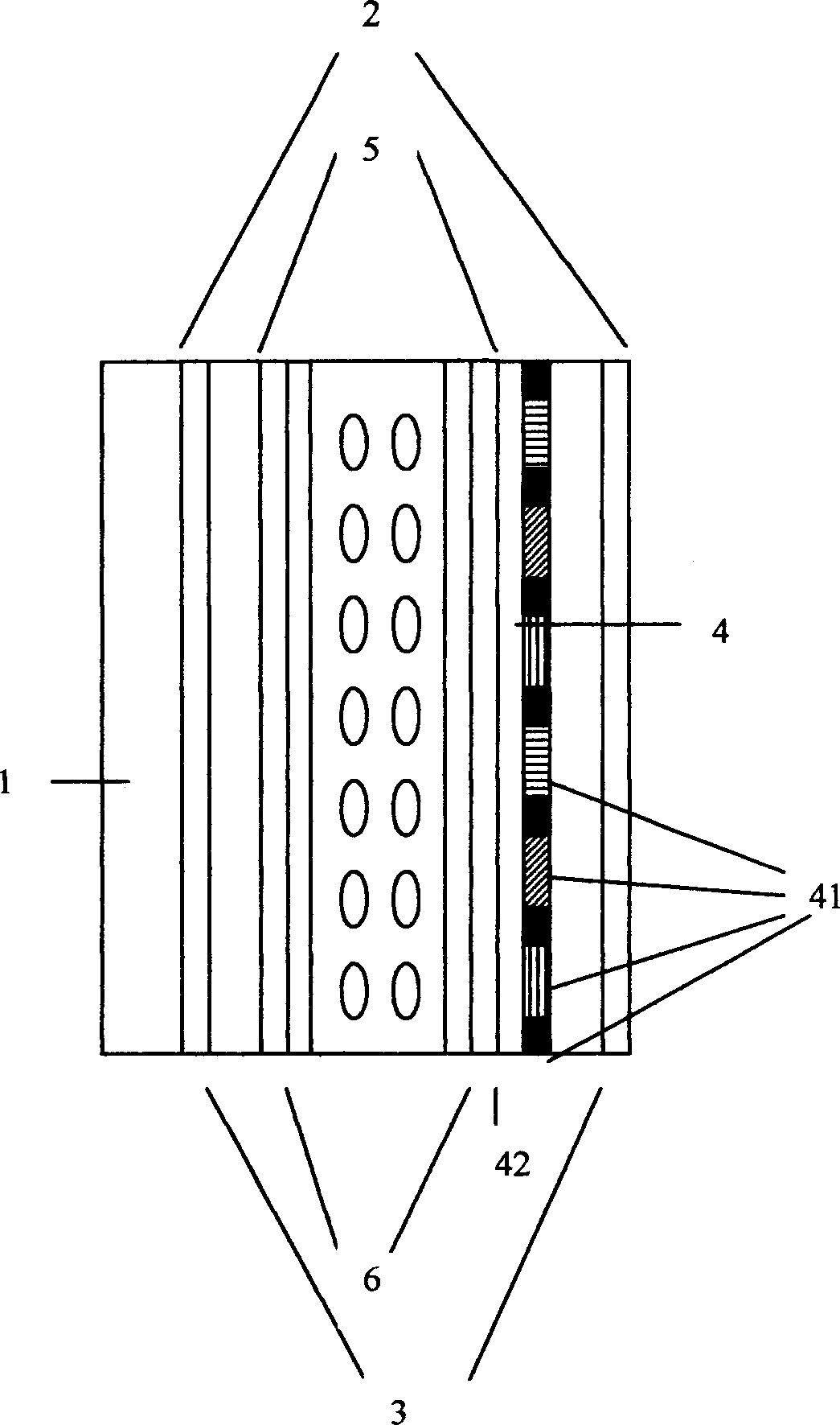
[0027] see Figure 4 , the liquid crystal display panel structure includes upper and lower polarizers 1, upper and lower glass substrates 2, ITO conductive layer 3, PI orientation layer 4, backlight module 5, and the external color filter 6 of the present invention is attached to the backlight module 5. Between the lower polarizer 1 and the lower polarizer 1, the alignment mark 1 as ...

Embodiment 2

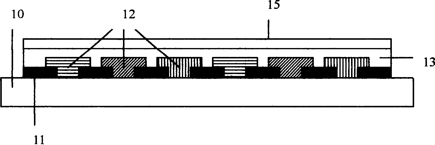
[0029] see Figure 5 , the difference between the external color filter in the second embodiment of the present invention and the external color filter in the first embodiment is that no protective layer is formed on the substrate 2 thereof. In addition, it should be noted that the protective layer outside the substrate and the OC layer can be selectively added, and the protective layer can be added simultaneously outside the substrate and the OC layer, or only on one side, or not on both sides. The protective layer may be a single layer or multiple layers.

[0030] see Image 6 The difference between the LCD panel structure of the second embodiment of the present invention and the LCD panel structure of the first embodiment is that the external color filter 6 is attached between the lower polarizer and the lower glass substrate. In addition, it should be noted that there are multiple options for the position of using the external color filter. In addition to the positions u...


PUM


Abstract

The present invention relates to one kind of external color filter for LCD panel and one LCD panel structure with the color filter. The external color filter has the structure including one substrate layer with BM and three color layers of R, G and B; one OC layer covering the substrate layer and one optional protecting layer on the OC layer. The independent color filter film may be combined with LCD panel through adhesion in one of the optional positions while ensuring the precise positioning of BM and three color layers of R, G and B to the ITO lines. The present invention has simplified color LCD panel manufacture, raised color filter utilization and lowered cost.

Description

【Technical field】 [0001] The present invention relates to an independent external color filter for a liquid crystal display panel, and a liquid crystal display panel structure using the independent external color filter. 【Background technique】 [0002] See figure 1 A color LCD panel mainly includes a backlight module 1, front and rear polarizers 2, upper and lower glass substrates 3, color filter film 4, ITO conductive layer 5 and PI alignment layer 6. Among them, the color filter film is made on one of the glass substrates, including BM, R, G, B three-color coloring layer 41 and OC protective layer 42. A conductive layer of ITO is sputtered on. It can be seen from this that the color filter film, the glass substrate and the ITO conductive layer are an integral structure, and the color filter film cannot be isolated as a separate product in the entire liquid crystal display manufacturing process. [0003] see figure 2 , the figure is figure 1 The schematic diagram of t...

Claims


Application Information

Patent Timeline
Patent Type & Authority Applications(China)
IPC IPC(8): G02F1/1335G02B5/23G02F1/133
Inventor 杨彧陈学刚
Owner 深圳市合力泰光电有限公司
Why Eureka
Try Eureka