
Vertical back light module

A backlight module, direct type technology, applied in the direction of optics, optical components, nonlinear optics, etc., can solve the problems of display defects, increased distance, uneven brightness of liquid crystal panel display, etc., to eliminate display defects and avoid excessive brightness , the effect of increasing the spread

Inactive Publication Date: 2006-10-18
HONG FU JIN PRECISION IND (SHENZHEN) CO LTD +1
View PDF0 Cites 15 Cited by
  • Summary
  • Abstract
  • Description
  • Claims
  • Application Information

AI Technical Summary

Problems solved by technology

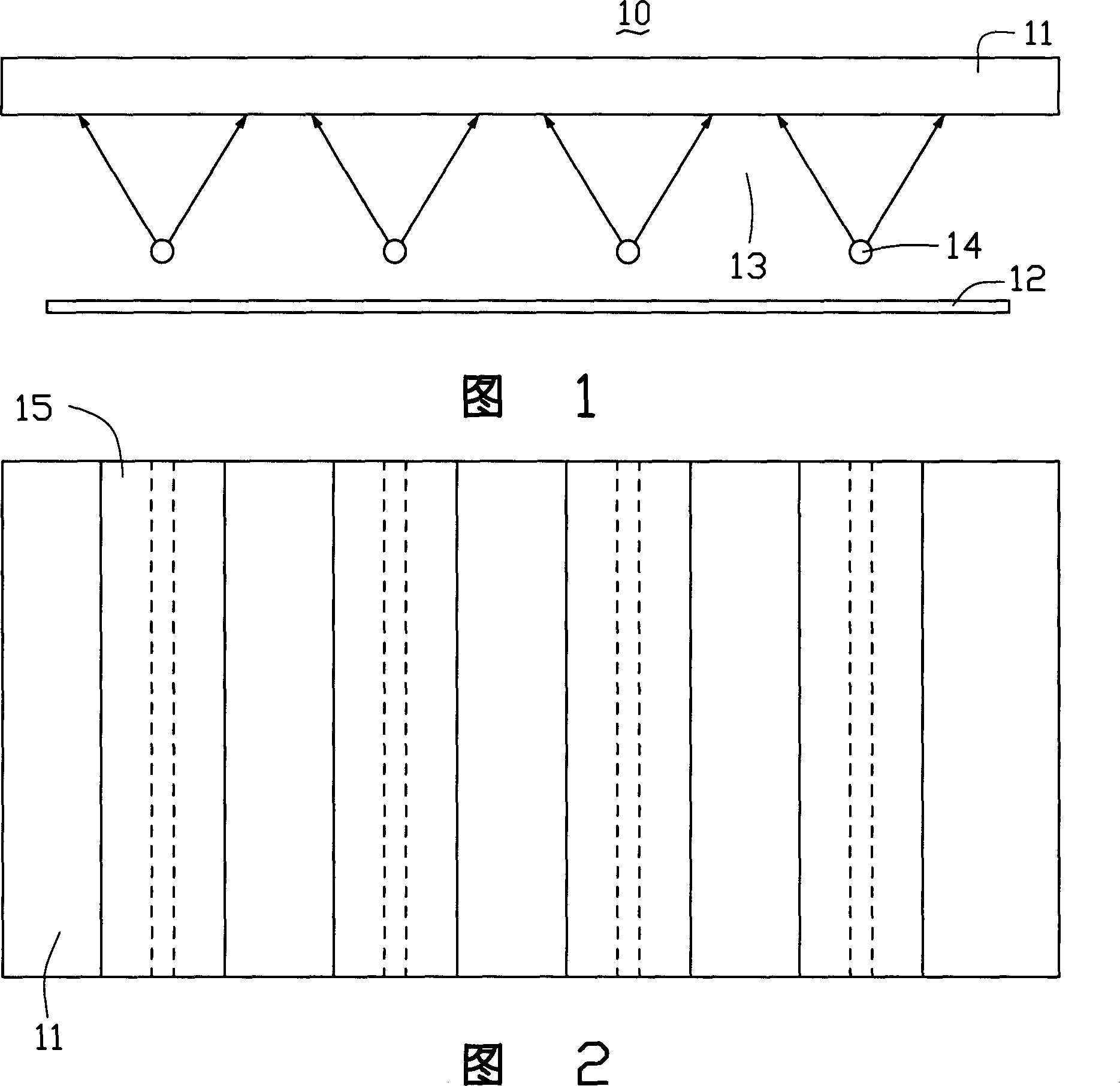
[0005] Because the light of cold cathode fluorescent lamps is anisotropic, and when the number of lamp tubes 14 is small, due to the high reflection effect of the reflector 12, when the backlight module 10 is turned on, the lamp tubes 14 will diffuse in the space above it. The position facing the lamp tube 14 on the board 11 has a higher brightness, and other positions have a lower brightness, thus reflecting the bright bands of the display, making the display brightness of the liquid crystal panel uneven and causing display defects. Figure 2 shows a schematic diagram of the bright bands. The dotted line in the figure shows the lamp tube located under the diffusion plate 11, and the bright band 15 is the area shown by the solid line in the figure
[0006] In order to eliminate this phenomenon and make the light shine to a larger area, it is necessary to increase the distance between the lamp tube 14 and the diffuser plate 11, which makes the volume of the direct-type backlight module 10 larger, which cannot satisfy thin requirements

Method used


Image

  • Vertical back light module
  • Vertical back light module
  • Vertical back light module

Examples


Embodiment Construction

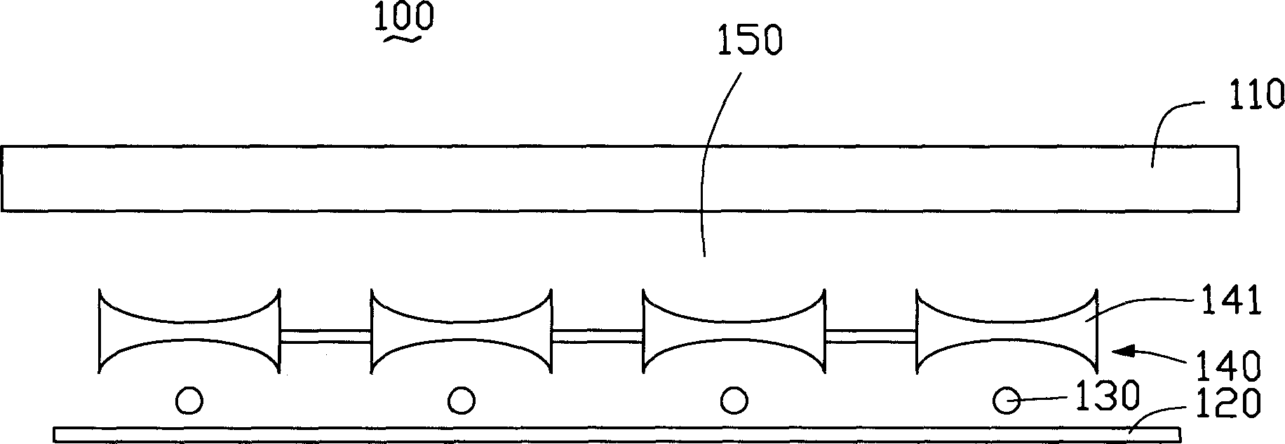
[0025] see image 3 , is a schematic diagram of the structure of the direct type backlight module according to the first embodiment of the present invention. The direct type backlight module 100 includes a diffuser plate 110 , a reflector plate 120 , a plurality of lamp tubes 130 and a diffuser 140 . The diffuser 110 is disposed on the reflector 120 and forms a chamber 150 with the reflector 120 . The lamp 130 is located in the chamber 150 and is a cold cathode fluorescent lamp or a light emitting diode.

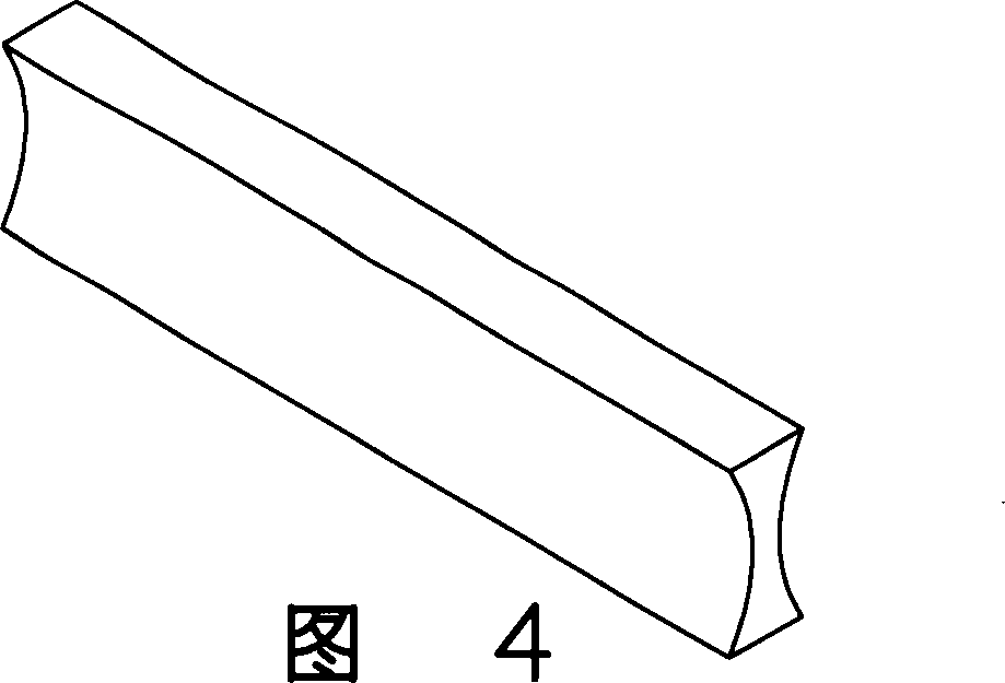
[0026] The astigmatism device 140 is located between the lamp tube 130 and the diffuser plate 110, which is a lens module, including a plurality of concave lenses 141, and each concave lens 141 corresponds to a lamp tube 130, because the concave lens 141 has the effect of astigmatism, each The light emitted by a lamp tube 130 is refracted by the concave lens 141 and diffused to increase, so that the area of ​​the light incident on the diffuser plate 110 can be increased. Th...


PUM


Abstract

The vertical back light module includes one reflecting plate, one diffusion plate, lamp tubes and one light diverging device. The diffusion plate is set on reflecting plate to form one holding chamber in between for holding the lamp tubes, and the light diverging device is set between the lamp tubes and the diffusion plate. The light diverging device may be one lens assembly including convex lenses corresponding to the lamp tubes separately, or one light conducting plate with refraction index gradually increased from the center to sides, or one prismatic lens.

Description

【Technical field】 [0001] The invention relates to a direct type backlight module. 【Background technique】 [0002] In recent years, with the colorization and enlargement of liquid crystal displays, their application fields are more extensive, such as notebook computers, various desktop computers, and LCD TVs. [0003] Since the liquid crystal display panel itself cannot emit light, it is a passive component and needs to use a light source system, such as a backlight module (Backlight Module), to provide a side light source for it to display screen images. [0004] A prior art direct-type backlight module is shown in FIG. 1. The direct-type backlight module 10 includes a diffuser 11 and a reflector 12, and a chamber 13 is formed between the reflector 12 and the diffuser 11. , a plurality of lamp tubes 14 are arranged in the chamber 13 . The lamp tube 14 is a cold cathode fluorescent lamp (CCFL), and the light emitted by it is diffused by the diffuser plate 11 and then projec...

Claims


Application Information

Patent Timeline
Patent Type & Authority Applications(China)
IPC IPC(8): G02F1/1335
CPCG02B5/02G02B5/0278G02F1/133606G02F1/133628G02F1/133607
Inventor 蔡坤荣
Owner HONG FU JIN PRECISION IND (SHENZHEN) CO LTD
Learn More